Site pages
Current course
Participants
General
Module 1: Introduction and Concept of Soil Erosion
Module 2: Water Erosion and Control
Module 3: Wind Erosion, Estimation and Control
Module 4: Soil Loss- Sediment Yield Estimation
Module 5: Sedimentation
Module 6: Topographic Survey and Contour Maps
Module 7: Land Use Capability Classification
Module 8: Grassed Waterways
Module 9: Water Harvesting
Module 10: Water Quality and Pollution
Module 11: Watershed Modeling
Keywords
Lesson 7 Gully Erosion
Gully erosion is an advance stage of rill erosion as rill erosion is the advanced stage of sheet erosion. It is the most spectacular form of erosion. Any concentration of surface runoff is a potential source of gully erosion. The Soil Conservation Society of America defines a gully as “a channel or miniature valley cut by concentrated runoff but through which water commonly flows only during and immediately after heavy rains. It may be dendritic or branching or it may be linear, rather long, narrow and of uniform width”. In India, the rate of soil erosion from gullies is 33 t/ha/yr in ravine regions (Shekinah and Saraswathy, 2005). The distinction between ravine, gully and rills is that of size. A gully is too large to be filled by normal tillage practices. A ravine is a deep narrow gorge. It is larger than a gully and is usually worn down by running water. It is estimated that about 4 million ha of land in India are affected by gully erosion (Michael and Ojha, 2012).
7.1 Development of Gullies
The main processes in the development of gullies are waterfall erosion and channel erosion. These two erosions are commonly found in the same gully. The extension of the gully head is usually by waterfall erosion; while the scouring of bottom and sides which enlarges the depth and width of gullies is by channel erosion. Gullies usually start with channel erosion. When an overfall develops at the head of the gully, the gully continues to develop by waterfall erosion. The waterfall erosion at gully head and advancement of the gully towards the upper edge of the watershed is shown in Fig. 7.1.
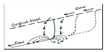
Fig. 7.1. Waterfall erosion at gully head.
The gully development is recognized in four stages:
Formation Stage: Scouring of top soil in the direction of general slope occurs as the runoff water concentrates. It normally proceeds slowly where the top soil is fairly resistant to erosion.
Development Stage: Causes upstream movement of the gully head and enlargement of the gully in width and depth. The gully cuts to the C-horizon of soil, and the parent materials are removed rapidly as water flows.
Healing Stage: Vegetation starts growing in the gully.
Stabilization Stage: Gully reaches a stable gradient, gully walls attain a stable slope and sufficient vegetation cover develops over the gully surface to anchor the soil and permit development of new topsoil.
7.2 Classification of Gullies
Gullies can be classified based on three factors viz. their size, shape (cross section) and formation of branches or continuation. The detailed classification is discussed below.
7.2.1 Based on Size (depth and drainage area)
Gully classification based on the size is presented in Table 7.1.
Table 7.1. Gully classification based on size
|
Classification |
Depth (m) |
Drainage area (ha) |
|
Small |
< 1 |
< 2 |
|
Medium |
1 to 5 |
2 to 20 |
|
Large |
> 5 |
> 20 |
7.2.2 Based on Shape
The classification of gullies based on shape is shown in Fig 7.2.
U-Shaped: These are formed where both the topsoil and subsoil have the same resistance against erosion. Because the subsoil is eroded as easily as the topsoil, nearly vertical walls are developed on each side of the gully.
V-Shaped: These gullies develop where the subsoil has more resistance than topsoil against erosion. This is the most common form of gully.
Trapezoidal: These gullies are formed where the gully bottom is made of more resistant material than the topsoil. Below the bottom of gully, the subsoil layer has much more resistance to get eroded and thus the development of further depth of gully is restricted.
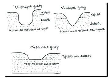
Fig. 7.2. Gully classes based on the shape of gully cross-section.
7.2.3 Based on the Formation of Branches or Continuation
Continuous Gullies: These gullies consist of many branches. A continuous gully has a main gully channel and many mature or immature branch gullies. A gully network is made up of many continuous gullies. A multiple-gully system may be composed of several gully networks.
Discontinuous Gullies: These may develop on hillsides after landslides. They are also called independent gullies. At the beginning of its development, a discontinuous gully does not have a distinct junction with the main gully or stream channel. Flowing water in a discontinuous gully spreads over a nearly flat area. After some time, it reaches the main gully channel or stream. Independent gullies may be scattered between the branches of a continuous gully, or they may occupy a whole area without there being any continuous gullies.
7.3 Principles of Gully Control
Generally, gullies are formed by an increase in surface runoff. Therefore, minimizing surface runoff is essential in gully control. The rate of gully erosion depends primarily on the runoff producing characteristics of the watershed, the watershed area, soil characteristics, size-shape and slope of gully etc. Watersheds deteriorate because of misuse of the land (man made changes), short intensive rainstorms, prolonged rains of moderate intensity, and rapid snow melts. The precipitation factors which turn into high runoff, develop flooding and form gullies. In gully control, the following three methods should be applied according to the order given:
Improvement of gully catchments to reduce and regulate the runoff rates (peak flows).
Diversion of surface water above the gully area.
Stabilization of gullies by structural measures and accompanying re-vegetation.
When the first and/or second methods are applied in some regions of the countries with temperate climates, small or incipient gullies may be stabilized without having to use the third method. On the other hand, in tropical and subtropical countries which have heavy rains (monsoons, typhoons, tropical cyclones, etc.); all three methods have to be applied for successful gully control.
7.4 Gully Control Measures
Preventing the formation of gully is much easier than controlling it once it has formed. One of the major steps in a gully control programme is to plan the control of runoff from the drainage area. The various methods employed for controlling runoff may be considered in the following order:
Retention of Runoff on the Drainage Area: It is possible through good crop management and applicable conservation practices such as contouring, strip cropping, bunding, terracing etc. Where contour bunds are used, runoff is greatly reduced. On cultivated areas, small and medium sized gullies can also be reclaimed by placing a series of earthfills across the gully.
Diversion of Runoff Around the Gullied Area: The most effective control of gullies is by complete elimination of runoff from the gullied area. This can be obtained by diverting runoff from the gully, causing it to flow at a non- erosive velocity to a suitable outlet. Terraces and diversion ditches are generally used for diverting runoff from its natural outlet. Terraces are very effective in the control of small gullies on cultivated fields or even medium size shallow gullies. If the slope above a gully is too steep for terracing, or if the drainage area is pasture or woodland, diversion ditches may be used to keep the runoff out of the gully.
Conveyance of Runoff through the Gully: If it is not possible to either retain or divert the runoff, then runoff must be conveyed through the gully itself. This is possible only if vegetation can be established in the gullies, or if soil conservation structures are built at critical points to give primary control.
7.5 Classification of Gully Control Measures or Structures
Basically gully control structures are used to reduce soil erosion, control sedimentation, and harvesting water. Gully control measures are mainly of two types.
7.5.1 Biological or Vegetative Measures
7.5.1.1 Anti-Erosion Crops
These crops stabilize gully. Crops produced provide supplementary income.
7.5.1.2 Changing Gully into Grassed Waterway
Small and medium size gullies can be converted into grassed waterways. In practice, gully is shaped and suitable species of grasses are grown. Channel cross-section should be broad and flat, to keep water spread uniform over a wide area.
7.5.1.3 Sod Flumes
It may be successfully used to control overfall in gullies with head < 3 m and area <10 ha. The design of sod flume is shown in Fig 7.3. It serves the purpose of preventing further waterfall erosion by providing a protected surface over which the runoff may flow into the gully. Slope varies with the soil type, size of watershed, height of overfall and type of sod used. 4:1 is the steepest slope considered for its design. To maintain a non-erosive velocity, flume should be wide enough. The maximum depth of flow over the flume should not exceed 30 cm.
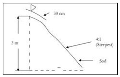
Fig. 7.3. Sod flume.
7.5.1.4 Sod Strip Checks
These checks are best adapted to small gullies with small to medium sized watersheds. These checks cannot be used in gullies with very steep grades. Strips are laid across gully channel (Fig. 7.4). Strips should have a minimum width of 30 cm and should extend up to gully sides at least 15 cm. Strip spacing usually varies from 1.5 to 2.0 m.
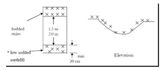
Fig. 7.4A. Sod strip checks.
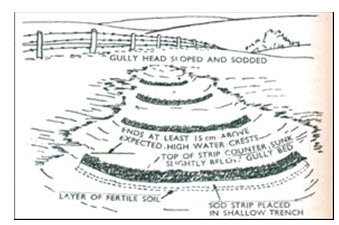
Fig. 7.4B. A series of sod-strip checks in a small gully. (Source: Agr. Handbook No. 61. USDA, SCS).
7.5.1.5 Low Sodded Earthfills
These are used as substitutes for temporary gully controlled structures in small and medium sized gullies. Already growing sods are cut along with soil mass and combined together to form earth fill dams (Fig. 7.5). They are constructed with a maximum height of 45 cm, upstream (u/s) side slope of 3:1 and downstream (d/S) side slope of 4:1.
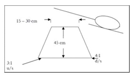
Fig. 7.5 Low sodded earthfills.
7.5.1.6 Trees, Shrubs etc.
Trees, shrubs etc. are used to stabilize severely eroded gullied area. Generally gullied area is fenced and trees are grown. A plant spacing of 1 × 1 m, 1.2 × 1.2 m or a maximum of 2 × 2 m should be maintained.
7.5.2 Engineering Measures (Temporary and Permanent)
7.5.2.1 Temporary Gully Control Structures (TGCS)
TGCS have a life span of 3 to 8 years and they are pretty effective where the amount of runoff is not too large. These are made of locally available materials. Basic purposes they serve are to retain more water as well as soil for proper plant growth and prevent channel erosion until sufficient vegetation is established on the upstream side of the gully. TGCS are of many types:
Woven wire check dams
Brush dams
Loose rock dams
Plan or slab dams
Log check dams
Boulder check dams
7.5.2.2 Permanent Gully Control Structures (PGCS)
If the erosion control programmer requires bigger structure, then PGCS are used. They include:
Drop spillway
Drop-inlet spillway
Chute spillway
Permanent earthen check dams
7.6 Design Criteria of TGCS
The overall height of a temporary check shouldn’t ordinarily be more than 75 cm. An effective height of about 30 cm is usually considered sufficient. Also, sufficient freeboard is necessary.
Life of the check dams under ordinary conditions should be in between 3 to 8 years.
Spillway capacity of check dams is generally designed to handle peak runoff that may be expected once in 5 to 10 year return period.
Since the purpose of check dams in gully control is to eliminate grade in the channel, check dams theoretically should be spaced in such a way that the crest elevation of one will be same as the bottom elevation of the adjacent dam up-stream.
As an integral part of most of the checks dams, an apron or platform of sufficient length and width must be provided at the down-stream end to catch the water falling over the top and to conduct it safely without scouring.
7.6.1 Woven Wire Check Dams
Woven-wire check dams are small barriers which are usually constructed to hold fine material in the gully (Fig. 7.6).
General:
Used in gullies of moderate slopes (not more than 10 percent) and small drainage areas that do not have flood flows which carry rocks and boulders.
Help in the establishment of vegetation for permanent control of erosion.
Dam is built in half-moon shape with the open end up-stream.
The amount of curvature is arbitrary: but an off-set equal to 1/6th of the width of gully at the dam site is optimum.
Construction:
To construct a woven-wire dam, a row of posts is set along the curve of the proposed dam at about 1.2 m intervals and 60-90 cm deep.
Heavy gauge woven wire is placed against the post with the lower part set in a trench (15-20 cm deep), and 25-30 cm projected above the ground surface along the spillway width.
Rock, brush or sod may be placed approximately up to a length of 1.2 m to form the apron.
For sealing the structure, straw, fine brush or similar material should be placed against the wire on the upstream side upto the height of spillway.
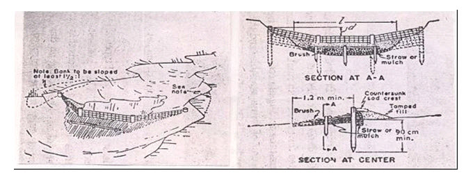
Fig. 7.6. Woven wire check dams. (Source: Agr. Handbook No. 61. USDA, SCS).
7.6.2 Brush Dams
General:
Cheap and easy to build, but least stable of all types of check dams.
Best suited for gullies with small drainage area.
Center of the dam is kept lower than the ends to allow water to flow over the dam rather than around it (Fig. 7.7).
Construction:
For a distance of 3-4.5 m along the site of the structure, sides and bottom of the gully are covered with thin layer of straw or similar fine mulch.
Brushes are then packed closely together over the mulch to about one half of the proposed height of dam.
Several rows of stakes are then driven crosswise in the gully, with rows 60 cm apart, and stakes 30-60 cm apart in the rows.
Heavy galvanized wire is used to fasten the stakes in a row, as well as to firmly compress the brushes in places.
Sometimes large stones are also placed on top of brush to keep it compressed and in close contact with the bottom of the gully.
Major weakness is the difficulty of preventing the leaks and constant attention is required to plug openings of appropriate size with straw as they develop.
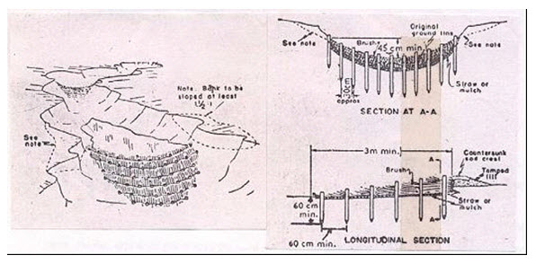
Fig. 7.7. Brush dam. (Source: Agr. Handbook No. 61. USDA, SCS).
7.6.3 Loose Rock Dams
Loose rock dams made of relatively small rocks are placed across the gully (Fig. 7.8). The main objectives for these dams are to control channel erosion along the gully bed, and to stop waterfall erosion by stabilizing gully heads. Loose stone check dams are used to stabilize the incipient and small gullies and the branch gullies of a continuous gully or gully network. The length of the gully channel is not more than 100 m and the gully catchment area is 2 ha or less. These dams can be used in all regions.
General:
Suitable for gullies with small to medium size drainage area.
Used in areas where stones or rocks of appreciable size and suitable quality are available.
Flat stones are the best choice for dam making.
Stones can be laid in such a way that the entire structure is keyed together.
If round or irregular shaped stones are used, structure is generally encased in woven-wire so as to prevent outside stones from being washed away.
If the rocks are small, they should be enclosed in a cage of woven-wire.
Construction:
A trench is made across the gully to a depth of about 30 cm. This forms the base of the dam on which the stones are laid in rows and are brought to the required height.
The center of the dam is kept lower than the sides to form spillway.
To serve as an apron, several large flat rocks may be countersunk below the spillway, extending about 1 m down-stream from the base of the dam.
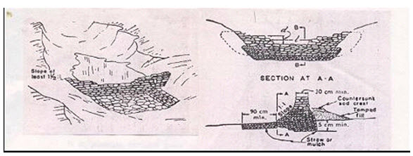
Fig. 7.8. Loose rock dam. (Source: Agr. Handbook No. 61. USDA, SCS).
7.6.4 Plank or Slab Dam
General:
These dams are suitable in areas where timber is plentiful, and dam can be constructed with much less labor as compared to other types of temporary structures.
These dams can generally be used in gullies with larger drainage area.
Construction:
The planks are placed across the gully to form the dam. If the planks are not close fitting, straw or grass may be used for sealing purposes.
A suitable opening for the spillway notch is made over the headwall. On the up-stream face, a well tempered earth fill is made.
On the down-stream, the apron may be made of loose rock, brush, sod or planks.
7.6.5 Log Check Dam
They are similar to plank or slab dams. Logs and posts used for the construction are placed across the gully. They can also be built of planks, heavy boards, slabs, poles or old railroad ties. The main objectives of log check dams are to hold fine and coarse material carried by flowing water in the gully, and to stabilize gully heads. They are used to stabilize incipient, small and branch gullies generally not longer than 100 m and with catchment areas of less than two hectares. The maximum height of the dam is 1.5 m from the ground level. Both, its downstream and upstream face inclination are 25 percent backwards. The spillway is rectangular in shape. In general, the length and depth of spillway are one to two meters and 0.5 to 0.6 m respectively (Fig. 7.9).
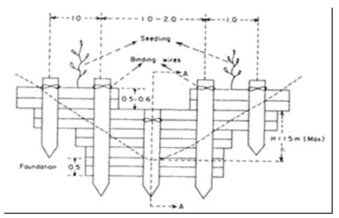
Fig. 7.9A. Front view of the first log check dam. (Source: Agr. Handbook No. 61. USDA, SCS).
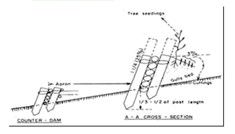
Fig. 7.9B. A-A cross-section of the first log check dam and counter dam. (Source: Agr. Handbook No. 61. USDA, SCS).
7.6.6 Boulder Check Dams
Boulder check dams placed across the gully are used mainly to control channel erosion and to stabilize gully heads. In a gully system or multiple-gully system all the main gully channels of continuous gullies (each continuous gully has a catchment area of 20 ha or less and its length is about 900 m) can be stabilized by boulder check dams. These dams can be used in all regions. The maximum total height of the dam is 2 m. Foundation depth must be at least half of the effective height. The thickness of the dam at spillway level is 0.7 to 1.0 m (average 0.85 m), and the inclination of its downstream face is 30 percent (1:0.3 ratio); the thickness of the base is calculated accordingly. The upstream face of the dam is usually vertical. If the above-mentioned dimensions are used, it is not necessary to test the stability of the dam against overturning, collapsing and sliding. The dimensions of the spillway (Fig. 7.10) should be computed according to the maximum discharge of the gully catchment area. The form of the spillway is generally trapezoidal.
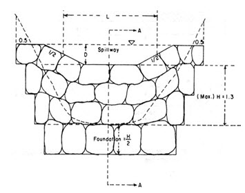
Fig. 7.10. Front view of the boulder check dam. (Source: Agr. Handbook No. 61. USDA, SCS).
Problem 7.1: Design the notch dimensions of a wooden slab dam to carry a peak flow of 0·6 m3/sec. The notch has rectangular opening. Width of gully channel is 2·5 m.
Solution
Q = 0·6 m3/sec = 600 litres/sec
Length, L, of notch = width of gully channel
= 2·5 m = 250 cm
Q = 0·0171 LH3/2
Substituting the values in the formula,
600 = 0·0171 x 250 x H3/2
H = 27·01 cm, say 27 cm
Assume a freeboard of 5 cm
Total depth of notch = 27 + 5 = 32 cm
The design dimensions of the notch are: length 2·5 m; total depth 32 cm.
Keywords: Gully erosion, Permanent structures, Temporary structures, Vegetative measures.
References
USDA, SCS, Agriculture Handbook No. 61 (1954). A Manual on Conservation of Soil and Water, Handbook for Agricultural Workers. USDA, Washington, D.C. 208 p.
Suggested readings
Michael, A. M., and Ojha, T. P. (2012). Principles of Agricultural Engineering. Vol 2, Jain Bros., 655 p.
Shekinah, D. E., and Saraswathy, R. (2005). Impacts of soil erosion by water- A review. Agric. Rev., 26 (3): 195-202.
Last modified: Wednesday, 18 December 2013, 10:48 AM