Site pages
Current course
Participants
General
Module 1: Introduction and Concept of Soil Erosion
Module 2: Water Erosion and Control
Module 3: Wind Erosion, Estimation and Control
Module 4: Soil Loss- Sediment Yield Estimation
Module 5: Sedimentation
Module 6: Topographic Survey and Contour Maps
Module 7: Land Use Capability Classification
Module 8: Grassed Waterways
Module 9: Water Harvesting
Module 10: Water Quality and Pollution
Module 11: Watershed Modeling
Keywords
Lesson 8 Drop Spillway
The drop structure is a weir structure, is limited to a maximum drop of 3 m and it is not a favorable structure where temporary spillway storage is desired to obtain a large reduction in the discharge at or d/s from the structure.
8.1 Permanent Gully Control Structures (PGCS)
PGCS, built of masonry, reinforced concrete or earth are efficient supplemental control measures in soil and water conservation. They are helpful in situation where vegetative measures or temporary structures fail to serve the purpose of controlling the concentration of runoff or reclaim a gully. PGCS are generally used in medium to large gullies with medium to large drainage area. PGCS are designed to handle runoff from the heaviest rains that may be expected once in 25 to 50 years or more depending upon the estimated life of the structure. Three basic permanent structures, generally employed in stabilizing gullies are:
Drop spillway
Drop inlet spillway
Chute spillway
8.2 Salient Features of PGCS
1. The main functions of PGCS are:
a) To halt the advance of over-fall at gully head,
b) To stabilize the grade so that a gully can be changed to vegetative waterway.
2. A gully control structure must not only have sufficient capacity to pass the design discharge, but the kinetic energy of discharge must also be dissipated within the confines of the structure in a manner and to a degree that will protect both the structure and the downstream channel from damage.
3. Two primary causes of failure of permanent structures are:
a) Insufficient hydraulic capacity and
b) Insufficient provision for energy dissipation.
8.3 Planning for Design
These structures must be designed after careful investigations of various factors influencing the characteristics of runoff approaching the structure (with reference to specific site conditions), the downstream flow characteristics and other specific requirements. There are no standard solutions which can be applied to all the problems encountered in the field. The design should include analysis of all the factors affecting the work. Basic data needed are:
Topographic map of the contributing watershed and the adjoining downstream area,
Information on soil.
Information on rainfall.
Existing land use pattern.
Preliminary investigations consisting of:
Reconnaissance of area,
Collection and analysis of available data and
Outline survey are pre-requisites in the overall planning of a permanent structure.
This helps the designer to study alternative site locations and to establish the techno-economic feasibility of the project. In the absence of adequate data, a safe design requires conservative assumptions. However, every effort should be made to collect all the available data. The more dependable the data, the smaller is the margin of over design and more economical will be the resulting structure.
8.4 Design Procedure
The design procedure of a PGCS may be divided into three phases:
Hydrologic design
Hydraulic design
Structural design
8.4.1 Hydrologic Design
It involves the determination of the design runoff rates and volumes which the structure is expected to handle.
Prediction of design peak runoff rates and flood volumes includes the study of the factors influencing the runoff characteristics of rainfall and watershed.
It is designed to handle runoff from the heaviest rain expected once in 25 to 50 years or more, depending upon the estimated life of structure.
For the design of spillway for flood protection structures like drop inlet spillway information on total runoff volume, inflow-outflow, reservoir stage and storage characteristics are important.
Flood routing procedure is employed in designing the spillways of drop inlet structures.
The Rational method of predicting peak runoff rate can be employed for designing drop structures and chute spillways.
8.4.2 Hydraulic Design
It involves the study of the requirements of the dimensions of the structure, in order to handle the estimated peak runoff through drop and chute structures.
It also involves the study of the effects of flow on the upstream and downstream reaches of the channel and the dissipation of the kinetic energy produced by the drop in the water surface elevation.
8.4.3 Structural Design
It provides the required strength and stability to the component parts of the structure. It involves the analysis of the various forces acting on the structure. The forces are:These forces disturb the equilibrium of the structure and give rise to internal stress, which should be effectively resisted by the material with which the structure is constructed.
a. The water pressure (static and dynamic) which acts on the structure.
b. The forces developed due to the outflow over the structure.
c. The effect of water flow underneath the structure (seepage, sub-surface flow).
These forces disturb the equilibrium of the structure and give rise to internal stress, which should be effectively resisted by the material with which the structure is constructed.
The structure must be stable under the action of the external forces and be able to withstand the sliding forces resulting from its own weight.
8.5 Basic Components of PGCS
- These components can be divided into three groups:
a) Inlet: Water enters the structures through the inlet, which may be in the form of a box or weir in a wall.
b) Conduit: The conduit receives the water from the inlet and conducts it through the structure. It restricts the water to a definite channel. The conduit may be closed in the form of a box channel or it may be open as in a rectangular channel.
c) Outlet: Its function is to discharge the water into the channel below at a safe velocity. The outlet should provide for the dissipation of kinetic energy of the discharge within the confines of the structure.
8.6 Drop Spillway
It is a weir structure, in which flow passes through the weir opening, fall or drops on an approximately level apron or stilling basic and then passes into the downstream channel. Its use is limited to a maximum drop of 3 m. It is mainly used at the gully bed to create a control point. Several such drop structures are constructed across the gully width throughout the length at fixed intervals. The series of such structures, develop a continuous break to flow of water, causing deposition of sediments and thus filling the gully section. Sometimes, the drop structures are also used at the gully head to pass the flow safely and controlling the gully head. The different components of drop structures are shown Fig. 8.1.
8.6.1 Components and Functions
-
Head wall: It acts as a front wall against runoff flow in the drop spillway. It is constructed across the gully width. A notch of suitable size is also made at the top in the headwall for easy water conveyance. Rectangular notch is most commonly used. The size of the notch should be sufficient to allow the water very safely.
-
Head Wall Extension: It is the extended portion of head wall into the gully sides. It permits stable fill and prevents piping (due to seepage) around the structure. Its main function is to provide structural strength against sliding of the structure and also to prevent the flow of water from the sides of the drop spillway.
-
Wing Walls: These are constructed at the rear end of the structure with some inclination, usually at 45o from the vertical. These walls are extended up to the gully sides and perform the function of preventing the flow backward into the space left between gully wall and side wall of the structure. They provide stability to the fill and protect the gully banks and surface.
-
Cut-off Walls: These are constructed to provide structural strength against sliding of the structure. They increase frictional resistance of the structure which opposes the force causing the slide. In other words, cut-off walls act as a key for the structure, prevent piping under the structure besides reducing uplift and sliding.
-
Toe Walls: Prevent undercutting of apron.
-
Side Walls: These are constructed in the side along the gully walls. They guide the water and protect the fill against erosion. The function of the side walls is to prevent splashing of water over the gully banks and also to confine the water flow within the apron.
-
End Sills: These are the elevated portion of rear end of the apron. Its main function is to obstruct the water from directly moving into the channel below. They also raise the tail water level to create hydraulic jump and to dissipate the energy of the flowing water.
-
Longitudinal Sills: These are constructed in the apron section. They are constructed lengthwise parallel to the side walls. The sills are useful to make the apron stable.
-
Apron: It is one of the main downstream components of the straight drop spillway as it receives the gully flow with high velocity and changes the flow regime so as to minimize the soil erosion on the downstream channel. It includes several elevated blocks to make the apron surface rough. This feature of apron is responsible for dissipating the maximum kinetic energy of falling water by creating hydraulic jump. As a result the velocity of outflow water is significantly reduced.
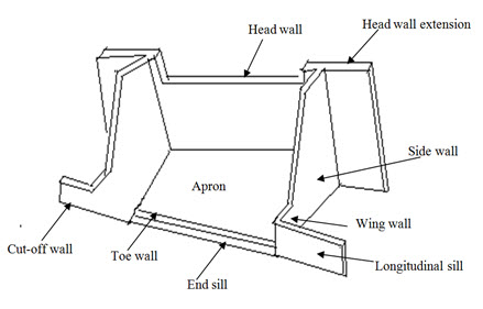
Fig. 8.1. Drop spillway. (Source: -------------)
The drop structure is used to control the velocity of runoff in a channel by allowing the water to fall from higher elevation to much lower elevation. The main three purposes of drop spillways are as follows:
To provide a transition between a broad or flat waterways and ditch or gully section.
To raise the flow line to allow formation of sufficient soil depth for vegetative growth where bottom of the gully is at risk.
To raise the flow line of the waterway so as to provide drainage in case of wet waterways.
8.6.2 Uses of Drop Spillway
To control gradient in either natural or constructed channels, To control tail-water at the outlet of a spillway or conduit.
To serve as a reservoir spillway where the total drop is relatively low.
To serve as inlet and outlet structures for tile drainage system in conjunction with gradient control.
To use as grade stabilization in lower reaches of waterways and outlets.
To use as erosion control, to protect the roads, buildings etc.
Straight drop spillway as an outlet in tile drainage system and for releasing the irrigation water into the field in irrigation system.
In the reservoir, for letting out the water through low height drop spillway of less than 3 m,
For controlling irrigation in the water distribution system and
As an outlet for disposing surface water from large areas, especially with drainage ditches.
8.6.3 Material for Construction
For most soil conditions, drop spillways may be built of any of the construction materials adapted for use in hydraulic structures. It may be concrete, masonry, concrete blocks etc. Reinforced concrete is most widely used and has been very satisfactory in terms of long life and low annual cost. In case a number of structures are involved, the selection of material should be based on the required life span of structures and annual cost comparison, which includes maintenance, of the structures built of different available material.
8.6.4 Advantages
Stability: It is very stable and likelihood of serious structural damage is remote.
Non-Clogging of Weir: As rectangular weir is used in this case, there is less likelihood of clogging by debris.
Maintenance cost is low.
It is relatively easy to construct and economical.
Standardization: The designs may be standardized which result in savings in engineering and constructional costs.
The danger of undermining by rodents is not possible in this structure.
8.6.5 Disadvantages
Use is limited to a maximum drop of 3 m. They may be costlier than other structure.
It is not a favourable structure where it is desired to use temporary spillway storage to obtain a large reduction in the discharge at or downstream from the structure.
In the areas where discharge is less than 3 m3/s, the construction of straight drop spillway proves to be costly affair, and thus should not be preferred.
If the gully grade below the structure is not stable then it is impossible to construct a drop spillway.
8.7 Design of Drop Spillway
In general, the hydraulic structures fail mainly due to their insufficient hydraulic capacity and lack of provision for dissipating the energy of falling water into the structure. That is why, design of these structures is done considering not only to have sufficient discharge handling capacity, but also for dissipating the kinetic energy of the falling discharge within the structure in such a manner that will protect the structure and downstream channel from scouring.
8.7.1 Hydrologic Design
It involves the estimation of design runoff rate and flood volume which the structures have to handle safely. Runoff rate is calculated by the rational method.
8.7.2 Hydraulic Design
The design consists of determining the length of crest (L), and depth (h) of the weir to provide required capacity and to maintain an adequate freeboard under free flow condition. The design of drop structure is done using the following steps.
(a) Inlet Design: Straight drop spillway consists of a straight type inlet due to which it is named as straight drop spillway. This type of inlet is most suitable for wide and shallow gullies to handle small to medium flows. To calculate the inflow capacity of straight drop spillway, the following weir formula may be used:
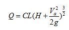 (8.1)
(8.1)
where, Q = peak discharge rate (m3/s) which is to be handled by the structure; L = Length of crest (m); H = head over the crest (m); = mean velocity of approach (m/s), C = coefficient of discharge. The value of C commonly used is 1.72. Thus, substituting the value of C in the above equation we have,
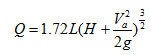 (8.2)
(8.2)
The above formula can only be applied if the crest of the weir is not submerged to a depth greater than dc/3 (dc is critical depth, ) by the tail water i.e. free flow condition is maintained. If the flow becomes submerged then the coefficient of discharge alters from the value of 1.72. The remaining two parameters i.e. length of crust (L) and depth of weir (h) are calculated as:
 (8.3)
(8.3)
 (8.4)
(8.4)
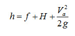
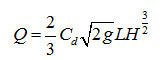
Another formula can be used for the calculation of the inflow capacity for submerged flow is given as:
 (8.5)
(8.5)
where, = coefficient of discharge and its value varies with the entrance condition (0.6); g = acceleration due to gravity (9.81 m/s2). By substituting the value of Cd and g in the above equation we have,
![]() (8.6)
(8.6)
By applying the above equation, L and H are determined using trial and error method to satisfy the Q value. A free board in the range of 15 to 30 cm is added to H to get the height of the side wall over the crest.
(b) Outlet Design: Outlet design is made with the considerations that the kinetic energy gained by the sheet of flowing water while falling from the crest of gully head to the downstream side of the structure must be dissipated and/or converted into potential energy. The preliminary calculations to design the outlet are performed by using the following two terms:
i) Froud Number: It may be calculated by the following formula:
 (8.7)
(8.7)
where, F = Froud number (dimensionless); v = velocity of flowing water entering into the apron to create the jump (m/s); d = depth of flow at entrance (m).
When F = 1,![]() , under this condition, the flow is said to be in critical state. If F < 1 or ,
, under this condition, the flow is said to be in critical state. If F < 1 or , ![]() the flow is referred as sub-critical flow. In this case gravity force is dominant which results in reduction of flow velocity. Similarly, if F > 1 or ,
the flow is referred as sub-critical flow. In this case gravity force is dominant which results in reduction of flow velocity. Similarly, if F > 1 or , ![]() the flow is super critical flow. In this state, the inertial forces become more dominant than the gravity force causing increase in the flow velocity. In outlet design, attempts are made to to convert the flow velocity to sub-critical range, by creating hydraulic jump inside the outlet.
the flow is super critical flow. In this state, the inertial forces become more dominant than the gravity force causing increase in the flow velocity. In outlet design, attempts are made to to convert the flow velocity to sub-critical range, by creating hydraulic jump inside the outlet.
ii) Hydraulic Jump: Depth of flow increases when flow changes from super-critical to sub-critical state. This increase in depth of flow over a very short length is known as hydraulic jump. In the process of development of hydraulic jump, a high degree of turbulence is created which is responsible for dissipating the energy.
(c) Design of Component Parts:
i) Height of transverse sill (S):
 (8.8)
(8.8)
ii) Height of headwall (HB): HB = F + S (8.9)
iii) Height of headwall extension (HE): HE = F + S + h (8.10)
iv) Minimum length of headwall extension (E): E = 3h + 0.6 or 1.5 F whichever is more. (8.11)
v) Minimum length of apron (LB): Whichever is more,
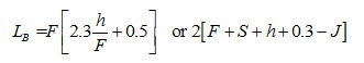 (8.12)
vi) Height of side wall and wing wall at the junction (J). Whichever is greater,
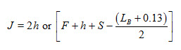 (8.13)
vii) Depth of cutoff wall (c) and toe wall (T):
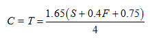 (8.14)
8.7.3 Structural Design
It involves the determination of strength and stability of different parts of the structure. The various forces which act on the structure are mainly static water pressure, force due to overflow and effect of water flow below the structure (i.e. seepage and sub-surface flow). The structural design comprises estimation of horizontal pressure (equivalent fluid pressure), uplift pressure, contact pressure and factor of safety.
Keywords: Drop spillway, Hydraulic design, Hydrologic design, Structural design.
Suggested readings
Michael, A. M., and Ojha, T. P. (2012). Principles of Agricultural Engineering. Vol 2, Jain Bros., 655 p.
Suresh, R. (2009). Soil and Water Conservation Engineering, Standard Publishers Distributors, 951 p.
Last modified: Wednesday, 18 December 2013, 11:20 AM