Site pages
Current course
Participants
General
Module 1: Introduction and Concept of Soil Erosion
Module 2: Water Erosion and Control
Module 3: Wind Erosion, Estimation and Control
Module 4: Soil Loss- Sediment Yield Estimation
Module 5: Sedimentation
Module 6: Topographic Survey and Contour Maps
Module 7: Land Use Capability Classification
Module 8: Grassed Waterways
Module 9: Water Harvesting
Module 10: Water Quality and Pollution
Module 11: Watershed Modeling
Keywords
Lesson 9 Drop Inlet Spillway
A drop inlet or shaft spillway is one in which the water enters through a horizontally positioned circular or rectangular box type riser or inlet and flows to some type of outlet protection through a circular (horizontal or near horizontal) conduit. The drop inlet spillway is ideally suited to conditions when there is need to control the downstream channel flow by providing a temporary storage upstream of the structure. It consists of an earthen dam and a pipe spillway. The dam provides the temporary storage of runoff from the contributing watershed while the spillway permits the design discharge to pass downstream (Fig. 9.1). It is adapted where drop is > 3.0 m. The drop inlet structure (Fig. 9.1) consists of the inlet, conduit and the outlet. Where the inlet is funnel shaped, this type of structure is often called as Morning glory or Glory hole spillway.
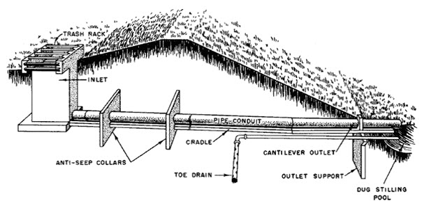
Fig. 9.1. Drop inlet spillway and its components.
(Source: Michael and Ojha, 2012).
Advantages
Drop inlet structures are used in gullies towards the downstream part to create storage of water.
These structures not only help in protecting gullies but also create water storage.
The stored water could be useful for irrigation or other farm use purposes.
A large number of drop inlet structures will have a retarding effect on downstream flows. A reduction in the sediment load could also occur.
An earthen embankment helps in storing the water and the drop inlet essentially lets out the excess water safely.
These are frequently used for headwater flood control and as outlets for farm ponds and reservoirs, silt detention reservoirs and settling basins.
They are suitable as gully control structures for the stabilization and control of advancing gully heads when the gully is more than 3 m deep.
They are relatively simple to build.
9.1 Design of Drop Inlet Spillways
The design consists of hydrologic and hydraulic designs.
9.1.1 Hydrologic Design
The hydrologic design of the drop inlet structure consists of knowing both the peak rate of runoff expected and also the inflow hydrograph. The latter is needed as temporary storage of water is created in case of these structures. The outflow will not be same as the inflow like in drop or chute spillways.
9.1.2 Hydraulic Design
To understand the hydraulic design of the structure, the different types of flow that occur in the conduit are to be considered. The flow through the structure could be controlled first by the inlet and latter by the conduit. A typical discharge characteristic curve is shown in Fig. 9.2. To calculate the inflow capacity of straight drop inlet spillway, the following weir formula is used.
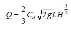 (9.1)
(9.1)
where, Q = peak discharge rate to be handled by the structures (m3/s); g = acceleration due to gravity (9.81 m/s2); H = head over the crest (m); Cd = coefficient of the discharge (0.6). A free board is also added to H. Generally 15 to 30 cm of free board is added to the calculated value of H.
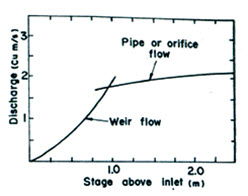
Fig. 9.2. Discharge characteristic curve of a drop inlet spillway.
(Source: Murty and Jha, 2011)
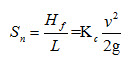
The flow through the conduit is governed by the slope given to it. There is also loss of head due to friction (Hf) during the flow and it is given by:
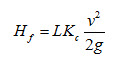
where L = length of the pipe (m); v = velocity of flow (m/s); Kc = head loss coefficient.
The slope of the pipe is given by:
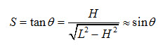 (9.3)
(9.3)
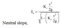
Neutral slope (Sn) is a hydraulic slope in which the head loss due to friction is equal to the head loss due to elevation change in the conduit.
 (9.4)
(9.4)
Different flow conditions possible are shown in Fig. 9.3 (a), (b) and (c). When the conduit has a slope less than the neutral slope and the inlet is submerged the conduit will flow full (Fig. 9.3a). Pipe flow condition prevails and the capacity of the conduit under the conditions shown in Fig. 9.3 (a) and (c) is given by:
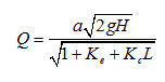 (9.5)
(9.5)
where a = area of cross section of the conduit (m2) and Ke = coefficient of entrance losses.
If the conduit is at greater than neutral slope and the outlet is not submerged (Fig. 9.3b), the flow will be controlled by the inlet section of the conduit. In such a case the discharge (Q) is calculated using the orifice formula:
![]() (9.6)
(9.6)
where c = the coefficient of discharge for the orifice (obtained from hydraulic tables).
Using these formulae for the discharge characteristics of the drop inlet (shown in Fig. 9.2) is prepared. From the site conditions, the information relating to the stage (water level above the level of the inlet) and the storage capacity can also be determined. Using the inflow hydrograph, storage-capacity curve and the discharge characteristics of the structure, the outflow hydrograph of the structure can be worked out using the flood routing procedure. For the design storm hydrograph selected, the storage capacity and the discharge characteristics of the structure selected should be such that the temporary storage will not exceed the design depth for the embankment.
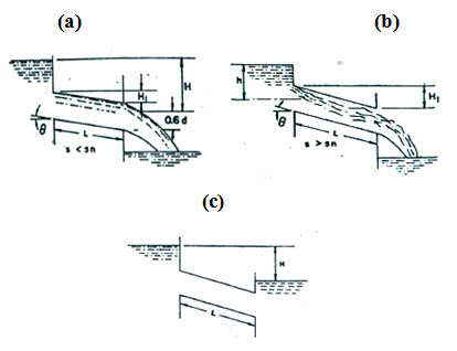 Fig. 9.3. Different flow conditions (a) Full free outfall pipe flow; (b) Part full: free outfall orifice flow; (c) Full: outfall submerged pipe flow in drop inlet spillway. (Source: Murty and Jha, 2011)
9.2 Components of Drop Inlet Spillway
The different components of the drop inlet spillway are shown in Fig. 9.4. The construction of the earthen embankment will have to be done in the same manner as the earth darns or embankments. Other features of the drop inlet spillway are as follows:
Anti-seep Collars: These are provided on the conduit pipe and are constructed using concrete masonry. These are necessary for control of seepages and prevention of failure due to piping. The total length of the seepage collars should be nearly 30 per cent of the total length of seepage and to get this length two or more seepage collars are provided. The anti-seep collars shall be placed within the saturated zone. The normal saturation zone may be determined by projecting a line at a slope of 4 horizontal to 1 vertical from the point where the normal water elevation touches the upstream slope of the fill to a point where this line intersects the invert of the pipe barrel. All soil fill located below this line may be assumed as saturated.
Cradle to the Conduit: To prevent uneven settlement and to develop hoop stress in the concrete pipes a cradle of masonry or concrete is provided to the conduit. Concrete pipes withstand more loads when hoop stress is developed than otherwise.
Emergency Spillway: If the runoff exceeds the design runoff, there is a danger of overtopping of the embankment and failure of the structure. To prevent such an occurrence, an emergency spillway is located on the embankment at the convenient location. The emergency spillway leads to downstream of the structure. The channel of the emergency spillway is protected with grass or stone pitching. The flood routing procedure gives the elevation at which the emergency spillway is to be located.
Stone Pitching: Stone pitching is recommended on the upstream side on the embankment and downstream side beyond the outlet to prevent soil erosion.
Filters: Sand and gravel filters are provided to help drainage and prevent piping.
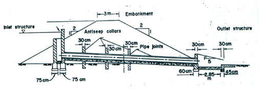
Fig. 9.4. Components of drop inlet spillway. (Source: Murty and Jha, 2011)
Problem 9.1
Determine the size of concrete pipe needed in a drop-inlet spillway for a peak flow of 2 m3/s and a total head of 3 m. Determine the slope to be given to the pipe for the pipe to flow full. Length of pipe = 12 m, entrance loss coefficient Ke = 0.5 and friction loss coefficient Kc = 0.03.
Solution
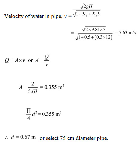
Neglecting the second term in denominator as it is very much less than 1.0.
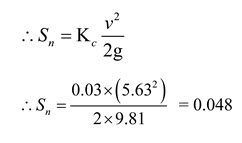
The downstream end of the pipe is kept 30 cm below the upstream end.
Actual slope, S = 0.3/12 = 0.025
As S < Sn, the pipe will flow full.
Keywords: Drop inlet spillway, Design, Emergency spillway, Discharge characteristic curve, Filters.
References
Michael, A. M., and Ojha, T. P. (2012). Principles of Agricultural Engineering. Vol 2, Jain Bros., 655 p.
Suresh, R. (2009). Soil and Water Conservation Engineering, Standard Publishers Distributors, 951 p.
Murty, V.V.N., and Jha, M. K. (2011). Land and Water Management Engineering, Kalyani Publishers, New Delhi, pp 600.
Suggested readings
Michael, A. M., and Ojha, T. P. (2012). Principles of Agricultural Engineering. Vol 2, Jain Bros., 655 p.
Suresh, R. (2009). Soil and Water Conservation Engineering, Standard Publishers Distributors, 951 p.
Murty, V.V.N., and Jha, M. K. (2011). Land and Water Management Engineering, Kalyani Publishers, New Delhi, pp 600.
Last modified: Friday, 20 December 2013, 5:02 AM