Site pages
Current course
Participants
General
Module 1: Introduction and Concept of Soil Erosion
Module 2: Water Erosion and Control
Module 3: Wind Erosion, Estimation and Control
Module 4: Soil Loss- Sediment Yield Estimation
Module 5: Sedimentation
Module 6: Topographic Survey and Contour Maps
Module 7: Land Use Capability Classification
Module 8: Grassed Waterways
Module 9: Water Harvesting
Module 10: Water Quality and Pollution
Module 11: Watershed Modeling
Keywords
Lesson 10 Chute Spillway
Chute (open channel or trough) spillway is a spillway whose discharge is conveyed from the upper reach of the channel or a reservoir to the downstream channel level through an open channel placed along a dam, abutment (supporting wall), or through a saddle. Chute structures are useful for gully head control and they could be used for drops upto 5 to 6 m. Chute spillways are constructed at the gully head to convey the discharge from upstream area of gully into the gully through a concrete or masonry open channel, when drop height exceeds the economic limit of drop structures. Chute spillway has more advantage than a drop spillway, when a large runoff volume is required to be discharged from the area. Flow in a chute spillway is at super-critical velocities.
10.1 Components of Chute Spillway
The chute spillway consists of the following three design components (Fig. 10.1):
Inlet or Entrance Channel: The most common type of inlets used in chute spillways are the straight inlet, box type inlet and sometimes side channel inlet also. The box type inlet is generally used in a situation when straight type inlet is not sufficient to carry the runoff at the desired drop.
Channel Section or Conduit: In chute spillway, the rectangular type conduits are mostly common. The side walls of conduit confine the flow rate and discharge distribution. The top edge of side walls is constructed in such a way that it may be flushed with the embankment slope. The vertical curve section is continued through the channel in such a manner so that it conveys and guides the discharge to the lower elevation without erosion.
Outlet: The outlet dissipates the energy of the flowing water and provides non-erosive velocity downstream. Straight apron type outlets are most commonly used in small gully control structures.
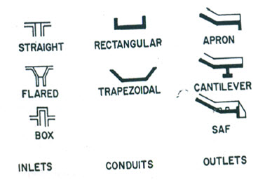
Fig. 10.1. Components of Chute Spillway. (Source: Michael and Ojha, 2012)
10.2 Applicability
In general, chute spillways are used whenever a channel is to be constructed down a steep slope.
They are preferred over drop spillways when the drop exceeds the economic limits of the latter.
It is superior to a drop inlet spillway when large discharges are required to be conveyed. When there is no opportunity to provide temporary storage, the chute spillway with its inherent high capacity is preferred over the drop inlet spillway.
Chute spillways are frequently used in combination with earth dams to drop water farther than is feasible with drop structures. The capacity of a chute spillway is not reduced due to sedimentation at the outlet.
However, sometimes there is a danger that rodents may undermine the structure and in poorly drained locations seepage may endanger the foundations.
10.3 Material for Construction
A chute spillway usually requires less masonry or concrete than a drop structure of the same capacity and drop.
To minimize problems of settling and undermining, chute spillways are constructed on foundations on solid ground or on fill that has been carefully compacted under controlled conditions.
Reinforced concrete, brick, or stone masonry are used for chute construction.
10.4 Design Features
Design of a chute spillway includes the design of the inlet, the channel section and the outlet.
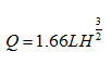
Inlet: The design procedure for inlets is the same as described under drop spillways. The discharge that the spillway is expected to convey is determined from hydrological data. The capacity of a chute spillway is usually controlled by the inlet section. The details of the inlet structure are shown in Fig. 10.2. The inlets convey and guide the designed discharge and provide cutoff of flow by piping under and around the chute channel. To calculate the inflow capacity of chute spillway, the following weir formula may be used:
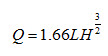 (10.1)
where, Q = peak discharge rate (m3/s) which is to be handled by the structure; L = Length of crest (m) and H = head above the crest (m).
Velocity of flow (v) is given by:
 (10.2)
where hf = frictional head loss over the apron (m); h = total drop.
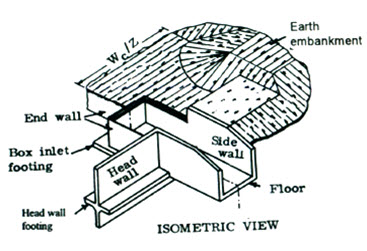
Fig. 10.2. Rectangular Weir Box Inlet for Chute Spillways.
(Source: Michael and Ojha, 2012)
Channel Section: Design of channel cross-section is similar to the design of open channel, in which bottom width, top width, side slope and depth are determined for a given discharge rate. For this purpose, Manning’s formulae is used.
Outlet: The design principle of outlet of chute spillway is similar to the design of outlet of drop structures (Fig. 10.3). The hydraulic jump is used as the means of energy dissipation. In the design of outlets using the hydraulic jump, the sequent-initial depths ratio (y2/y1) is important. Here y1 and y2 are the flow depths before and after the jump respectively.
In a rectangular channel the depth ratio is:
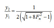 (10.3)
where, F1 = Froude number is given by  ; = the flow velocity before occurrence of hydraulic jump (m/s); g = acceleration due to gravity (m/s2).
The Saint Anthony Falls (SAF) stilling basin type outlet provides an adequate facility for dissipation of kinetic energy.
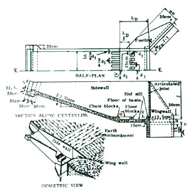
Fig. 10.3. Outline Section of Chute Spillway Provided with SAF Stilling Basin. (Source: Michael and Ojha, 2012)
10.4.1 Design of Saint Anthony Falls (SAF) Stilling Basin
The SAF stilling basin (Fig. 10.4) gives adequate performance for a range of Froude numbers varying from 1.7 to 17. The criteria for the design of SAF stilling basins are as follows:
Referring to Fig. 10.4, the dimensions of different components of SAF stilling basin are given as:
Length of stilling basin (LB):
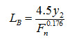 (10.4)
Width and spacing of the chutes and floor blocks = 0.75 y1; where y1 = height of the chute and floor blocks.
Spacing of floor blocks from upstream end of the stilling basin =
The floor blocks should not be closer than
from the side walls of the basin.
The location of the floor blocks should be fixed at downstream side from the openings between the chute blocks.
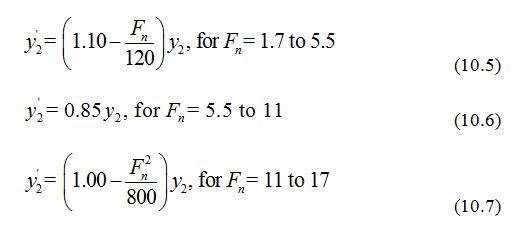
The height of the end sill should be equal to 0.07 y2, in which y2 stands for theoretical tail water depth, corresponding to initial flow depth y1.
The actual depth of tail water above the stilling basin may be computed by the following equation:
The height of side wall above the maximum tail water depth (y3) is given by:
The height of wing wall should be equal to the height of stilling basin’s side wall.
The top of the wing wall should be inclined at 1:1 slope.
The length of the wing wall should be equal to
The wing wall may be inclined at angle of 45˚ from the center line of the outlet.
In order to make the structures safe against sliding, a cutoff wall of nominal depth should be provided at the end of stilling basin.
In the design of stilling basin, the effect of entrained air should be neglected.
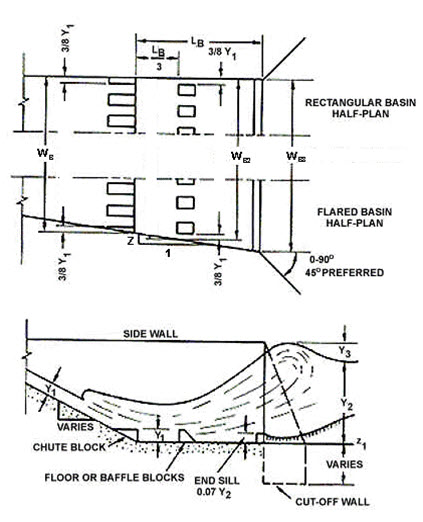
Fig. 10.4. Rectangular Weir Box Inlet for Chute Spillways.
(Source: Michael and Ojha, 2012)
Keywords: Chute Spillway, Entrance Section, Conduit, Outlet, SAF Stilling Basin.
References
Michael, A. M., and Ojha, T. P. (2012). Principles of Agricultural Engineering. Vol 2, Jain Bros., 655 p.
Suresh, R. (2009). Soil and Water Conservation Engineering, Standard Publishers Distributors, 951 p.
Murty, V.V.N., Jha, M.K., 2009, Land and Water Management Engineering, Fifth Edition, Kalyani Publishers, pp.600.
Suggested readings
Michael, A. M., and Ojha, T. P. (2012). Principles of Agricultural Engineering. Vol 2, Jain Bros., 655 p.
Suresh, R. (2009). Soil and Water Conservation Engineering, Standard Publishers Distributors, 951 p.
Murty, V.V.N., and Jha, M. K. (2011). Land and Water Management Engineering, Kalyani Publishers, New Delhi, pp 600.
Last modified: Friday, 20 December 2013, 5:17 AM