Site pages
Current course
Participants
General
Module 1. Basic Concepts, Conductive Heat Transfer...
Module 2. Convection
Module 3. Radiation
Module 4. Heat Exchangers
Module 5. Mass Transfer
Lesson-25 Introduction, Classification of Heat Exchangers, Logarithmic mean temperature difference
A heat exchanger is a device used for efficient transfer of heat between a hot and cold fluid when it is required to heat up a cold fluid or cool down a hot fluid. Both the fluids involved in heat exchange process are generally separated by a solid wall. Heat exchangers are used in wide range of applications such as
Heating and air conditioning systems
Automobile radiators
Cooling of internal combustion engines by a coolant
Boilers and condensers of a power plant
Chemical plants
Petroleum refineries
Classification of Heat Exchangers:
In order to meet the different and specific requirements of heat exchange between two fluids, different types of heat exchangers have been designed. However, heat exchangers are generally classified on the basis of following
Nature of Heat Exchange Process
Relative Direction of Flow of Fluids
Mechanical Design of Heat Exchanging Surface
Physical State of Heat Exchanging Fluids
A) Nature of Heat Exchange Process:
Depending upon the nature of heat exchange process, heat exchangers are categorized as
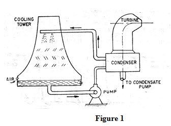
i) Direct Contact Heat Exchanger: In such a heat exchanger, hot and cold fluids exchange thermal energy by their physical mixing and there is a simultaneous transfer of heat and massas shown in Figure 1. Water cooling towers, Jet steam condensers are examples of direct contact heat exchanger.
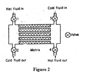
ii) Regenerator Type of Heat Exchanger: In regenerator heat exchanger, hot and cold fluids are brought in contact with a medium alternately with which they exchange heat. This is also known as storage type heat exchanger because heat transfer from hot fluid to cold fluid occurs through a coupling medium in the form of a solid matrix having a high heat capacity The hot fluid and cold fluid alternately flow through the matrix, the hot fluid storing heat in it and the cold fluid extracting heat from it. The arrangement is shown in Figure 2. During the first part of the cycle when hot fluid flows through the matrix, valves I and 4 are open and 2 and 3 are closed while during the latter part, valves 1 and 4 are closed and 2 and 3 are open.
iii) Recuperator:-In this type of heat exchanger, hot and cold fluids do not mix and exchange heat through a separating wall which also offers thermal resistance. The heat transfer process in such heat exchangers consists of
Convective heat transfer from hot fluid to wall
Conductive heat transfer from hot to cold surface of wall
Convective heat transfer from wall to cold fluid
Examples:- Boilers, automobiles, radiators
B) Relative Direction of Flow of Fluids:
Depending upon the relative direction of flow of fluids, heat exchangers are categorized as
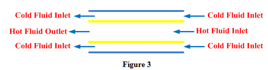
i) Parallel Flow: Hot and cold fluids enter the heat exchanger from the same side, flow in same direction and leave in same direction as shown in Figure 3.
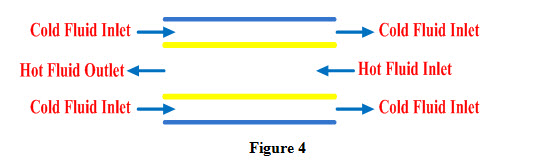
ii) Counter Flow: Hot and cold fluid enter from opposite side of heat exchanger, flow in opposite direction and leave in opposite direction as shown in Figure 4.
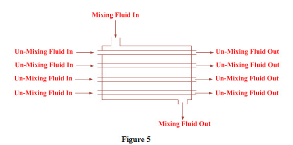
iii) Cross Flow: Hot and cold fluid flow in direction right angle to each other. If air is one of the fluids, pure counter flow is generally not preferred as shown in Figure 5.
C) Mechanical Design of Heat Exchange Surface
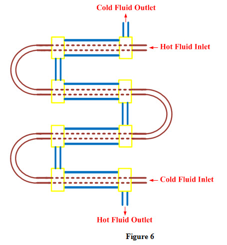
i) Concentric Tubes: Two concentric tubes are used, each carrying one of the fluids.
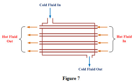
ii) Shell & Tube:- One of the fluid is carried through the bundle of tubes enclosed by a shell. The other fluid is forced through the shell and flows over the outside surface of the tubes as shown in Figure 7.
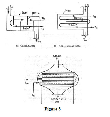
iii) Multi shell and Tube Passes:- Baffles are used to make the multi shell and Tube Passes heat exchanger as shown in Figure 8.
D) Physical State of Heat Exchanging Fluids:
Depending upon physical state of heat exchanging fluids, heat exchangers are categorized as
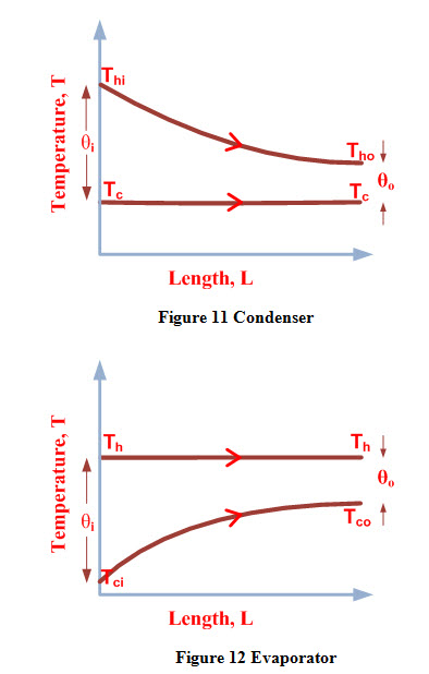
i) Condenser: Temperature of hot fluids remains constant all along the length of heat exchanger as it loses its latent heat while temperature of cold fluid increases
ii) Evaporator: Temperature of cold fluid remains constant as it gains its latent heat while temperature of hot fluid decreases.
Logarithmic Mean Temperature Difference
In a heat exchanger, thermal potential, responsible for heat exchange between the hot and cold fluids, changes as temperature of both the fluids changes along the length of the heat exchanger. In a parallel heat exchanger, thermal potential in a parallel heat exchanger is maximum at inlet; it decreases along the length and is minimum at the exit as shown in Figure 9. In a counter flow heat exchanger, maximum thermal potential exists at exit of the heat exchanger as shown in Figure 10.
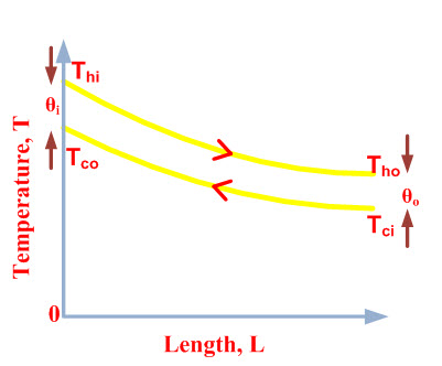
Figure 9 Parallel Flow Heat Exchanger
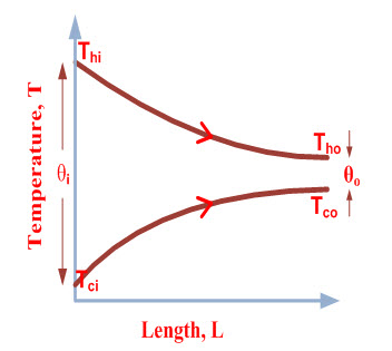
Figure 10 Counter Flow Heat Exchanger
However, in some heat exchangers such as condensers and evaporators, change in thermal potential along the length occurs only on account of change in temperature one of the fluids while temperature of the other fluid remains constant. Figures 11 and 12 represent variation of thermal potential along the length of a condenser and an evaporator
Heat transfer rate in a heat exchanger at a particular length is calculated by considering thermal potential at that length which is expressed as
Q = UA (Th – Tc) (1)
However, overall heat transfer in a heat exchanger is calculated by using average thermal potential and is generally represented by term logarithmic temperature difference. Therefore, overall heat transfer in heat exchanger can be expressed as
Q = UA (ΔT)m (2)
Where
U is overall heat transfer coefficient, W/ (m2-K)
A is heat transfer area, m2
(ΔT)m is mean temperature difference or logarithmic temperature difference, K
Last modified: Monday, 24 March 2014, 11:16 AM