Site pages
Current course
Participants
General
Module 1. Basic Concepts, Conductive Heat Transfer...
Module 2. Convection
Module 3. Radiation
Module 4. Heat Exchangers
Module 5. Mass Transfer
Lesson-27 Logarithmic mean temperature difference for counter and cross flow heat exchangers, Fouling or scaling of heat exchanger and Numerical problems
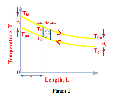
Consider a counter flow heat exchanger of length ‘L’ as shown in Figure 1 and let mh and mc are mass flow rates of hot and cold fluids respectively.
Thi and Tho are temperatures of hot fluid at inlet and outlet of heat exchanger respectively.
Tci and Tco are temperatures of cold fluid at inlet and outlet of heat exchanger respectively
cph and cpc are specific heats of hot and cold fluids respectively.
θi and θo represent temperature difference between hot and cold fluids at inlet and outlet of heat exchanger respectively and are expressed as
θi = Thi –Tco and θo = Tho –Tci (1)
Cph and Cpc are heat capacity rates of hot and cold fluid respectively.
Heat capacity rate of a fluid is defined as amount of heat required to increase temperature of a fluid by 1 oC and is expressed as
Cph = mh Cph, , Cpc = mc Cpc (2)
Consider an element of area dA and thickness dx at a distance ‘x’ from inlet of heat exchanger. Let Th and Tc are temperatures of hot and cold fluid at inlet of the element and θ represents temperature difference of hot and cold fluid at inlet of the element.
θ = Th –Tc (3)
Let dTh and dTc represent change in temperature of hot and cold fluids respectively during the flow through the element. Temperature difference between hot and cold fluid at inlet of element is expressed as
dθ = dTh - dTc (4)
During flow through the element, heat transferred is equal to heat lost by hot fluid and heat gained by cold fluid.
If dQ is the amount of heat transferred during flow of fluids through the element then
dQ = UdA θ = -mc cpc dTc = - mh cph dTh (5)
(-ve sign if temperature of fluid decreases along the length of heat exchanger)
Using equation (2), equation (5) can be written as
dQ = UdA θ = -Cc dTc = - Ch dTh (6)
From equation (6), we can write
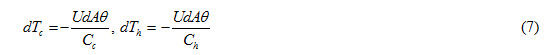
Substituting the values of dTc and dTh from equation (7) in equation (4), we get
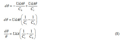
Integrating equation (8) between limits θi and θo
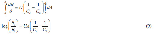
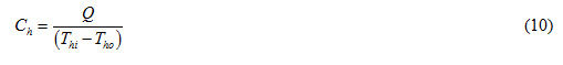
Heat lost by hot fluid during flow through heat exchanger is expressed as
Q = mh cph (Thi – Tho) = Ch (Thi – Tho)
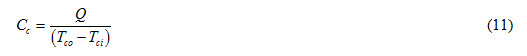
Heat gained by hot fluid during flow through heat exchanger is expressed as
Q = mc cpc (Tco – Tci) = Cc (Tco – Tci)
Substituting values of Ch and Cc from equations (10) and (11) in equation (9), we get
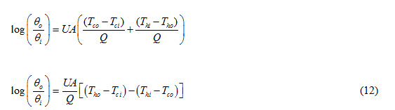
Using equation (1), equation (12) can be written as
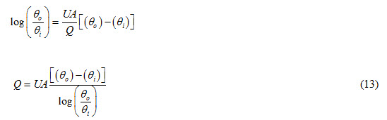
We know that in a heat exchanger, heat transfer between hot and cold fluids can be expressed as
Q = U A (ΔT)m (14)
Comparing equations (13) and (14), we can write
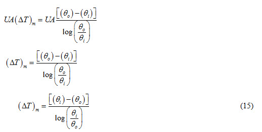
Equation (15) represents logarithmic mean temperature difference for a counter flow heat exchanger.
C. Cross Flow Heat Exchanger
In order to determine logarithmic mean temperature difference for a counter flow heat exchanger, following relationship is used.
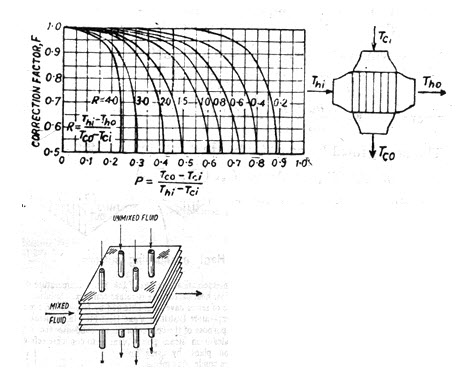
(LMTD)cross = F Χ (LMTD)counter
Where ‘F’ is a correction factor and is a function of geometry of heat exchanger and inlet as well as outlet temperatures of both the fluids. Values of correction factor for different arrangements of cross flow and multipass shell and tube heat exchangers are given in Figure 3.
Fouling Factor
Last modified: Tuesday, 25 March 2014, 9:31 AM