Site pages
Current course
Participants
General
Module 1. Basic Concepts, Conductive Heat Transfer...
Module 2. Convection
Module 3. Radiation
Module 4. Heat Exchangers
Module 5. Mass Transfer
Lesson-29 Effectiveness for counter flow heat exchanger and Numerical Problems
(b) Effectiveness for the Counter Flow Heat Exchangers:
From definition of effectiveness of a heat exchanger, we can write

Heat transferred in a heat exchanger can be expressed as
Q = Ch(Thi- Tho) = Cc(Tco-Tci)
Consider an element of area dA and thickness dx at a distance ‘x’ from inlet of a counter flow heat exchanger. Let dTh and dTc represent change in temperature of hot and cold fluids respectively during the flow through the element. Temperature difference between hot and cold fluid at inlet of element is expressed as
dθ = dTh - dTc (2)
If dQ is the amount of heat transferred during flow of fluids through the element then
dQ = UdA θ = - Cc dTc = - Ch dTh (3)
Substituting the values of dTh and dTc from equation (4) into the equation (3), we get
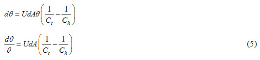
Integrating equation (5) between limits θi and θo
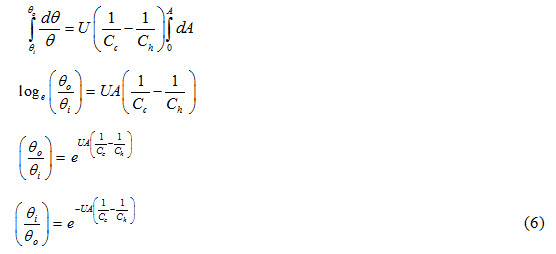
For a counter flow heat exchanger,
θi = Thi –Tco and θo = Tho –Tci
Equation (6) can be written as
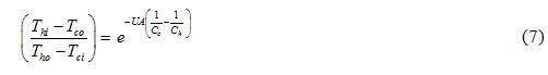
Using equation (1), values of Tho and Tco can be written as
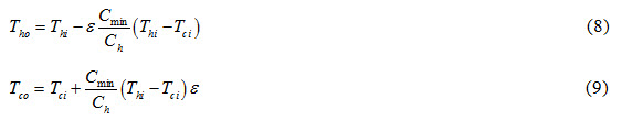
Substituting the values of Tho and Tco from equations (8) and (9) in equation (7), we get
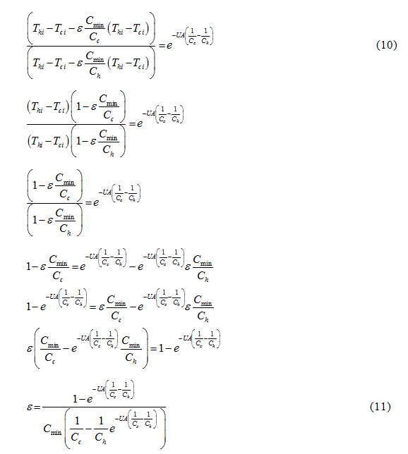
If Cc < Ch, then Cc = Cmin and Ch = Cmax equation (11) can be expressed as
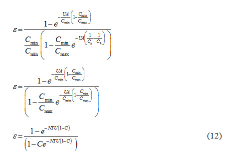
The following two important cases are considered
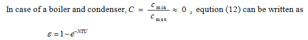
i) Boiler and Condenser:
ii) Gas Turbine:
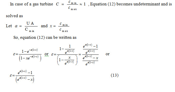
If the value of NTU = 1 then ε = 0.5 and heat exchanger becomes 50% efficient. It should be noted that the equations developed for the heat exchanger effectiveness are independent of the terminal temperatures of the fluid but are explicit functions of the dimensionless ratios NTU and ε. This enables one to plot ε verses NTU for selected values of Cmin/Cmax.
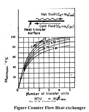
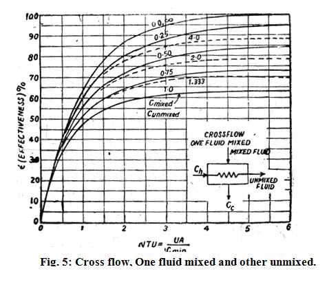
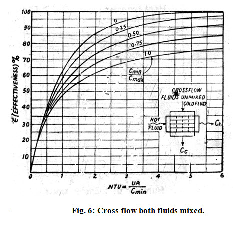
In many heat exchangers, the fluids flow at right angles to each other are known as cross flow. The effectiveness relationships for four common flow arrangements, parallel, counter, cross flow one fluid mixed and other unmixed and cross flow both fluid mixed represented in form of graphs by Keys and London are shown in figures (3), (4), (5), and (6) respectively.
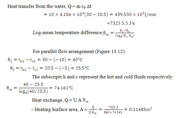
Example13.7 In a food processing plant, a brine solution is heated from -10°C to – 5.0°C in a double pipe parallel flow heat exchanger by water entering at 35°C and leaving at 20.5°C at the rate of 9 kg/min. Determine the heat exchanger area for an overall heat transfer coefficient of 860 W/m2 K. For water cp = 4.186 103 j/kgK.
Solution:
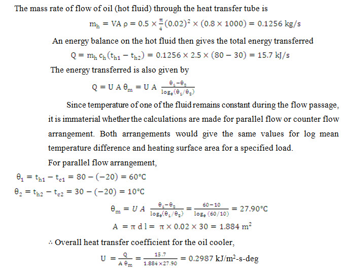
Example13.8 A tubular heat exchanger is to be designed for cooling oil from a temperature of 80°C to 30°C by a large of stagnant water which may be assumed to remain constant at a temperature of 20°C. The heat transfer surface consists of 30 m long straight tube of 20 mm inside diameter. The oil (specific heat= 2.5 kj/kg k and specific gravity=0.8) flows through the cylindrical tube with an average velocity of 50 cm/s Calculate the overall heat transfer coefficient for the oil cooler .
Solution:
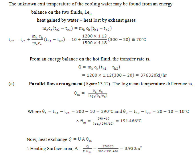
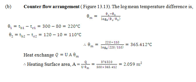
Example13.9 Exhaust gases (cp=1.12 kJ/kg-deg) flowing through a tubular heat exchanger at the rate of 1200 kg/hr are cooled from 300°C to 20°C. The cooling is affected by water (cp=4.18 kJ/kg-deg) that enters the system at 10°C at the rate of 1500 kg/hr. If the overall heat transfer coefficient is 500 kJ/m2-hr-deg, what heat exchanger area is required to handle the load for (a) parallel flow and (b) counter flow arrangement? .
Solution:
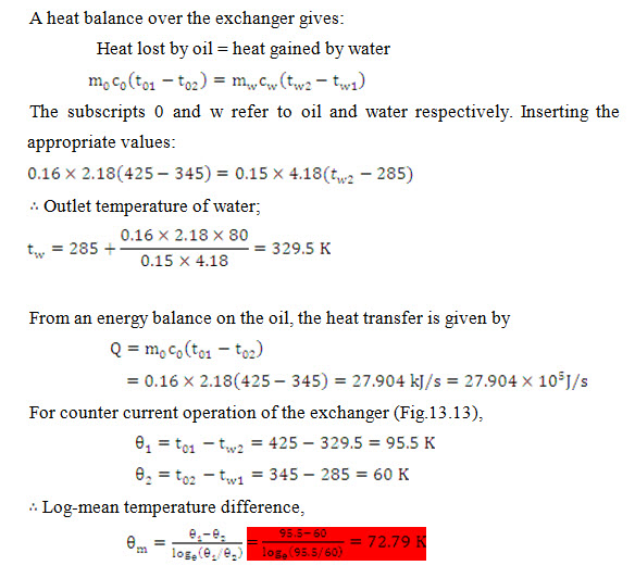
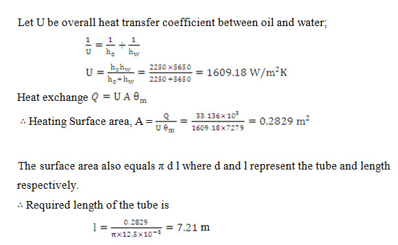
Example13.14 A counter-flow concentric tube heat exchanger is used to cool the lubricating oil of a large industrial gas turbine engine. The oil flows through the tube at 0.16 kg/s (cp=2.18 kJ/kgK), and the coolant water flows in the annulus in the opposite direction at a rate of 0.15 kg/s (cp=4.18 kJ/kgK).The oil enters the coolant at 425 K and leaves at 345 K while the coolant enters at 285 K. How long must the tube be made to perform this duty if the heat transfer coefficient from oil to tube surface is 2250 W/m2 K and from tube surface to water is 5650 W/m2 K? The tube has a mean diameter of 12 mm and its wall presents negligible to heat transfer.
Solution:
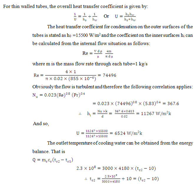
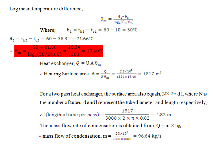
Example13.15 A one-shell, two-tube pass heat exchanger having 4000 thin wall brass tubes of 20 mm diameter has been installed in a stream power plant with a heat load of 2.3108 W. The stream condenses at 60°C and the cooling water enters the tubes at 10°C at the rate of 3000kg/s. Calculate the overall heat transfer coefficient, the tube length per pass, and the outer surfaces of the tubes as 15500 W/m2 K and the latent heat of stream as 2380 kJ/kg.
Further presume the following fluid properties:
c = 4180 j/kgK, μ=85510 -6 Ns/m2, k = 0.613 W/mK and Pr = 5.83
Solution:
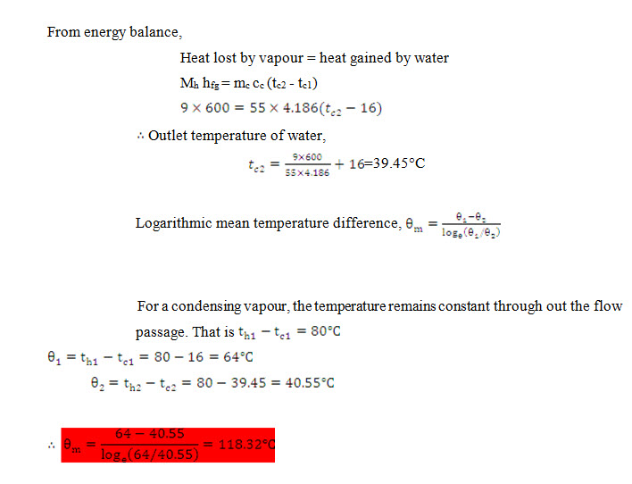
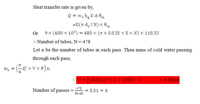
Example13.16 A heat exchanger is to be designed to condense 9 kg/s of an organic liquid (tsat=80°C; hfg=600 kj/kg) with cooling water at 16°C and at a flow rate of 55 kg/s. The overall heat transfer coefficient is 480 W/m2-deg. Calculate:
a) the number of tubes required. The tubes are to be of 25 mm outer diameter, 2 mm thickness and 5 m length.
b) the number of tube passes. The velocity of the cooling water is not to exceed 2 m/s
Solution:
Last modified: Wednesday, 26 March 2014, 4:57 AM