Site pages
Current course
Participants
General
Module 1. Basic Concepts, Conductive Heat Transfer...
Module 2. Convection
Module 3. Radiation
Module 4. Heat Exchangers
Module 5. Mass Transfer
Lesson-26 Logarithmic mean temperature difference for parallel flow heat exchanger, counter and cross flow heat exchangers, Overall Heat Transfer Coefficient for a Plane wall and Double Pipe Heat Exchanger
Overall Heat Transfer Coefficient
1. Plane Wall:
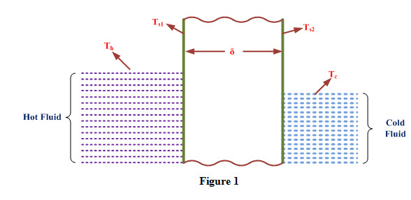
Consider a wall of thickness ‘δ’ made of a material having thermal conductivity ‘k’ and temperatures of wall surfaces are Ts1 and Ts2. On one side of the wall, a hot fluid at temperature Th is flowing and on the other side a cold fluid at temperature Tc is flowing as shown in Figure 1. Let hi and ho are convective heat transfer coefficients of hot and cold fluids with wall surfaces respectively. Under steady state conditions, heat transferred from hot fluid to wall surface is equal to heat conducted through the wall and it is equal to heat convected to the cold fluid from wall surface.
Heat transferred to wall surface by hot fluid is expressed as

Heat transferred through the wall by conduction is expressed as

Heat convected to cold fluid by wall surface is expressed as

Adding both sides of equations (1), (2) and (3), we get

We know that heat transfer in a heat exchanger can be expressed as
Q = UA (Th – Tc) (5)
Comparing equations (4) and (5), we can write
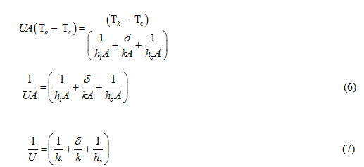
Equation (7) represents overall heat transfer coefficient for aplane wall.
2. Double Pipe Heat Exchanger
Consider a double pipe heat exchanger of length ‘L’ in which hot fluid and cold fluid are flowing through inner and outer pipes respectively as shown in Figure 2.
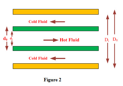
Let
hi and ho are convective heat transfer coefficients of hot and cold fluids with pipe surfaces respectively.
di and do are inside and outside diameters of inner pipe having thickness ‘δ’ and thermal conductivity ‘k’.

Ao= Π doL and Ai= Π diL
Di and Do are inside and outside diameters of outer pipe respectively.
Using equation (6), overall heat transfer coefficient, U for the arrangment can be expressed as

Substituting values of Ai , Ao and Am in equation (10), we get
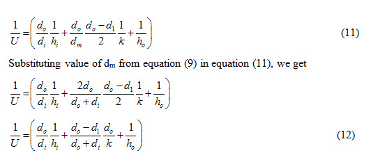
Equation (12) represents overall heat transfer coefficient with reference to outer surface of inner pipe of a double pipe heat exchanger.
Heat Transfer Analysis in Heat Exchanger
Heat is transferred from hot fluid to cold fluid in heat exchanger and it involves the following steps
i) Heat lost by hot fluid is expressed as
Qh = mh cph (Thi - Tho) (13)
ii) Heat gained by cold fluid is expressed as
Qc = mc cpc (Tco – Tci) (14)
iii) Heat transfer in heat exchanger is expressed as
Q = U A (ΔT)m (15)
From energy balance considerations, heat transferred in heat exchanger is equal to heat lost by hot fluid which is gained by cold fluid.
Q = Qh = Qc (16)
Performance of a heat exchanger can be analyzed by using following methods
1. Logarithmic Mean Temperature Difference or LMTD Method
2. Effectiveness of Number of Transfer Unit (NTU) Method
1. Logarithmic Mean Temperature Difference (LMTD) Method:
LMTD method is used when temperatures of both the fluids at inlet and outlet of the heat exchanger are known. Performance analysis by this method is carried out by making following assumptions:
i) Overall heat transfer coefficient, U remains constant along the length of heat exchanger.
ii) Specific heats and mass flow rates of both the fluids remain constant.
iii) Heat exchanger is perfectly insulated and no loss of heat occurs.
iv) Axial conduction along the pipes is negligible.
A. Parallel Flow Heat Exchanger:
Consider a parallel flow heat exchanger of length ‘L’ as shown in Figure 3 and let mh and mc are mass flow rates of hot and cold fluids respectively.
Thi and Tho are temperatures of hot fluid at inlet and outlet of heat exchanger respectively.
Tci and Tco are temperatures of cold fluid at inlet and outlet of heat exchanger respectively
cph and cpc are specific heats of hot and cold fluids respectively.
θi and θo represent temperature difference between hot and cold fluids at inlet and outlet of heat exchanger respectively and are expressed as
θi = Thi –Tci and θo = Tho –Tco (17)
Ch and Cc are heat capacity rates of hot and cold fluid respectively.
Heat capacity rate of a fluid is defined as amount of heat required to increase temperature of a fluid by 1 oC and is expressed as
Ch = mh Cph, , Cc = mc Cpc (18)
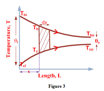
Consider an element of area dA and thickness dx at a distance ‘x’ from inlet of heat exchanger. Let Th and Tc are temperatures of hot and cold fluid at inlet of the element and θ represents temperature difference of hot and cold fluid at inlet of the element.
θ = Th –Tc (19)
Let dTh and dTc represent change in temperature of hot and cold fluids respectively during the flow through the element. Let dθ be the difference in change in temperature of hot and cold fluids during flow through the element and is expressed as
dθ = dTh - dTc (20)
During flow through the element, heat transferred is equal to heat lost by hot fluid and heat gained by cold fluid.
If dQ is the amount of heat transferred during flow of fluids through the element then
dQ = UdA θ = mc cpc dTc = - mh cph dTh (21)
(-ve sign if temperature of fluid decreases along the length of heat exchanger)
Using equation (18), equation (21) can be written as
dQ = UdA θ = Cc dTc = - Ch dTh (22)
From equation (22), we can write

Substituting the values of dTc and dTh from equation (23) in equation (20), we get
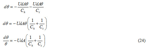
Integrating equation (24) between limits θi and θo
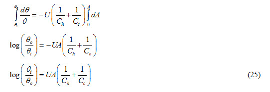
Heat lost by hot fluid during flow through heat exchanger is expressed as
Q = mh cph (Thi – Tho) = Ch (Thi – Tho)
Therefore,  (26)
(26)
Heat gained by cold fluid during flow through heat exchanger is expressed as
Q = mc cpc (Tco – Tci)
Therefore,  (27)
(27)
Substituting values of Ch and Cc from equations (26) and (27) in equation (25), we get

Using equation (17), equation (28) can be written as

Comparing equations (29) and (15), we can write
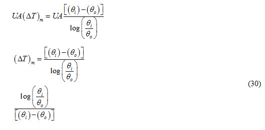
Equation 24.17 represents logarithmic mean temperature difference for a parallel flow heat exchanger.