Site pages
Current course
Participants
General
MODULE 1. Introduction to mechanics of tillage tools
MODULE 2. Engineering properties of soil, principl...
MODULE 3. Design of tillage tools, principles of s...
MODULE 4. Deign equation, Force analysis
MODULE 5. Application of dimensional analysis in s...
Module 6. Introduction to traction and mechanics, ...
Module 7. Traction model, traction improvement, tr...
Module 8.Soil compaction and plant growth, variabi...
LESSON 26. BALLASTING
26.1 BALLASTING
The tractive performance of a tractor can be improved, particularly on sandy loam soils, by ballasting, which adds weight to the drive wheels. It is important, however, that the tire manufacturer's recommended load, at normal inflation pressures, not be exceeded. The addition of ballast to a tractor is usually accomplished by adding wheel weights, adding front weights, and filling the tires with water. Adding too much ballast will result in excessive power loss due to increased rolling resistance, but insufficient ballast will cause power loss because of the increased wheelslip. The driving weight required over each traction tire can be determined from the traction prediction equations of Wismer and Luth (Chapter 4). It is important to match the tractor power, weight, speed, and draft force, For a two-wheel drive tractor, Gee-Clough et al. (1982) cite Reece (1970) as given the relationship
W*/P = 1.17/V ---------------------------------------- (5.1)
and for four-wheel drive tractors
W*/P = 0.82/V ---------------------------------------- (5.2)
where W* is the total tractor weight in kiloNewtons (kN), P the engine power (kW), and V the forward speed (m sec-1). Dwyer (1978) gave a relationship of the form
W/P* = 1.79/V ---------------------------------------- (5.3)
where W is the dynamic weight on the drive wheels (kN) and P* the total axle power (kW). This expression was obtained using average values from field tests. The equation is intended to give the weight on the drive tires per unit of axle power to ensure operation at maximum efficiency. Dwyer suggested operating at a slip of 0.1 (10%) and a coefficient of traction of 0.4.
If PTO power is to be used instead of axle power, then the losses between the axle and the PTO must be taken into account. Since PTO power levels are readily available from test reports, there is some practice value in relating dynamic weight to PTO power output. For a tractive efficiency of 0.7 and a coefficient of traction of 0.4, the PTO power, weight on the-driving wheels, and the vehicle speed can be related as follows (Bloome et al, 1983):
0.7(PTO power) = 0.4(weight on drive wheels)(vehicle speed) -------- (5.4)
This gives the relationship WV = 1.79 P* of Eq, (5.3). Other values for coefficient of traction and tractive efficiency can be used to give different-relationships. If a 4% loss is assumed between the PTO power and the axle power, then the relationship given in Eq. (5r5) can be written as
km hr-1 kN (PTO kW)-1 = 6.20 ---------------------------- (5.5)
Bloome et al. (1983) suggest that this equation is applicable to determining the optimum ballast for power-limiting conditions. The under-ballasted tractor is traction limited, and at a wheelslip of 20% and good soil conditions, a coefficient of traction of 0.5 is typical.
Assuming a tractive efficiency of 0.7 gives an expression
W/P* = 1.4/V ------------------------------------- (5.6)
or
km hr-1 kN (PTO kW)-1 = 4.84 -------------------------- (5.7)
Bloome et al. (1983) discussed ballasting recommendations for two-and four-wheel drive tractors. Dwyer (1978) and a tractor manufacturer recommend the same mass-to-power relationships for two- and four-wheel drive tractors operating at the same speed. There is also a case for having a slightly greater mass-to-power ratio for two-wheel drive tractors, since some axle force must be maintained on the unpowered front wheels to provide steering control. Alternatively, it can also be argued that four-wheel drive tractors can use slightly greater mass-to-power ratios since there is no rolling resistance loss associated with unpowered wheels. Bloome et al. (1983) conclude that ballasting recommendations should be the same for two- and four-wheel drive tractors operating at-the same speed. The ballast recommendations based on Dwyer (1978) are for utilization of full engine power. Tractors operating at less than full rated power will require some reduction in tractor ballast. This is perhaps best achieved for these part-load conditions by assuming appropriate values for tractive efficiency, coefficient of traction, and forward speed, and subsequently modifying Eqs. (5.5) and (5.7) in accordance with Eq. (5.4).
Gee-Clough et al. (1982) developed ballast recommendations based on the traction prediction equations developed by Gee-Clough et al. (1978). These equations were discussed in Chapter 4 and predict coefficient of traction and coefficient of rolling resistance, based on mobility number M. Using these equations, Gee-Clough et al. (1982) developed an approach for estimating the theoretical loss in tractive efficiency resulting from having drive tire loads greater or smaller than the optimum value.
The power transmitted by the drive wheels, P1 (kN), is given by
P1 = WCTV --------------------------------- (5.8)
where W is the dynamic load on the drive wheels (kN), CT the coefficient of traction, and V the forward speed (m sec-1), The maximum power that the wheels are able to transmit, P2 (kW), at any value of slip is given by
P2 = ηp* ------------------------------------ (5.9)
where η is the tractive efficiency and P* the total axle power (kW).
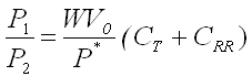
If P1= P2, then the power transmitted will be equal to the maximum possible at that value of slip, and
WCTV = ηp* ----------------------------- (5.10)
or
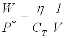 ----------------------------- (5.11)
In order for operation at maximum power to be achieved, the slip at which P1 = P2 has to be the slip at maximum efficiency. Gee-Clough et al. (1982) showed that for the range of mobility numbers normally encountered for soil conditions (8-30), the slip at which maximum efficiency occurs is 10%. If this represents the optimum condition, then
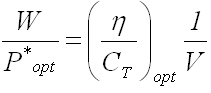 -------------------------------- (5.12)
combining Eqs. (5.11) and (5.12) gives
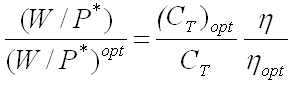 --------------------------- (5.13)
For preset values of wheelslip and mobility number, values of W/P*, CT, and η can be found. These can be compared to the optimum values and a curve of W/Wopt against η / η opt drawn. Gee-Clough et al. (1982) produced the diagram of this relationship, which is reproduced in Fig. 5.1. It is apparent that there is a desirable range for W/Wopt, but that it can be allowed to deviate from W/Wopt = 1, particularly at the increased values for mobility number.
If the power actually transmitted by the wheels, P1, is always less than the maximum power able to be transmitted, P2, at all values of slip, then the tractor will never be power limited. The conditions under which this would occur are calculated from Eq. (5.8) as
P1 = WCTV = WCTV0 (1 – i) -------------------- (5.14)
where V0 is the theoretical (no-load) forward speed. From Eq. (5.9),
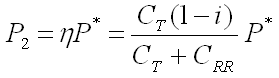 -------------------------- (5.15)
and
 ---------------------------- (5.16)
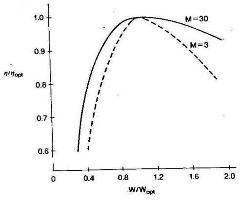
Fig. 5.1. Ratio η / η opt Vs. W/Wopt for mobility number M = 3 and M = 30 [from Gee-Clough et al. (1982)].
The expression WV0/P* is a dimensionless number, which is termed the ballast number by Gee-Clough et al. (1982). The tractor drive tires will never be able to deliver the power available if the ballast number is smaller than that required to give P1 = P2. This is the power-limited condition. Gee-Clough et al. (1982) showed that if the maximum slip is assumed to be 20%, then the minimum value for the ballast number to ensure the tires deliver the available power is 1.58. Thus
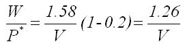 ----------------------------- (5.17)
This can be rewritten as
km hr-1 kN (PTO kW)-1 = 4.36 ------------------------------- (5.18)
Equation (5.18) provides for a ballast level 70% of that given for the optimum ballast in Eq. (5.5). Therefore, the minimum ballast recommendation should be at 70% of that for the optimum level. Experiments by Gee-Clough et at. showed no significant reduction in power output up to a maximum ballasting of 70% of the optimum. Thus an acceptable recommendation for the ballast is that the dynamic tire load should be 70-140% of the optimum value to avoid major losses in the output power at the drawbar. The maximum ballast can be written as
km hr-1 kN (PTO kW)-1 = 8.68 ------------------------------- (5.19)
To summarize:
1. The coefficient of traction at maximum efficiency can be assumed to be 0.38-0.4 for most soil conditions encountered in agriculture.
2. This level of coefficient of traction will give maximum efficiency at a slip of 10%.
3. The load on the drive tires should be based on axle power and working speed in accordance with Eq. (5.5). That is,km hr-1 kN (PTO kW)-1 = 6.20
The load on the tires is the dynamic tire load. It includes the static load and the weight transfer effect.
4. The minimum ballast for the traction-limited condition is given by a dynamic load that is 70% of the optimum. This is given by Eq. (5-20) as km hr-1 kN (PTO kW)-1 = 4.36.
5. The maximum ballast for the power-limited condition is given by Eq. (5.19) as km hr-1 kN (PTO kW)-1 = 8.68.
A weight transfer analysis specifically of four-wheel drive tractors was presented by Peters (1983), The equations developed were used to express the vehicle performance in terms of the rear axle. Figure 5.2 shows the free-body diagram used by Peters in analyzing the forces on a four-wheel drive tractor.
Summing moments about the rear axle gives
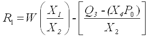 ----------------------------- (5.20)
where R1 is the front dynamic load, W the vehicle weight, Q3 the total axle torque ( = Q1 + Q2), and P0 the resultant drawbar pull.
The front static weight is given by the term W(X1/X2) and the load transfer component is given by Q3 – (X4P0)/X2
The ballast requirement can be determined from the coefficient of traction. Equations for coefficient of traction (which is also referred to as
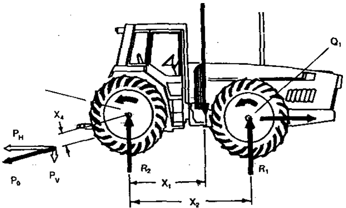
Fig. 5.2. Forces acting on a four-wheel drive tractor [from Peters (1983)].
the "dynamic ratio" and "pull ratio") were given in Chapter 4. The general expression for coefficient of traction is (Leviticus and Reyes, 1983)
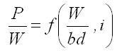
And P/W = (CT)max(1-e-k(bd/w)i) ----------------------------- (5.21)
where P is the drawbar pull, W the dynamic weight on the tire, b the tire section width, d the tire diameter, i the slip, (CT)max the constant equivalent to the maximum coefficient of traction, and K a constant related to the tire resilience (kN/m2). For a tire moving on soil, the K factor is taken to be equivalent to the cone index.
Leviticus and Reyes (1983) developed an expression termed the "tractive quotient" (TQ) from Eq. (5.21):
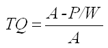
and thus
TQ = e-k(bd/w)i ------------------------------------------ (5.22)
This expression was used to evaluate the tractive response for different tire-loading factors. Tire loading is represented by the expression bd/W. Values for the constants A and K were obtained from the analysis of Nebraska tractor tests. The results were therefore only applicable to performance on concrete. As the tire-loading factor was increased, the coefficient of traction was found to increase at the same value of slip. However, the rate of increase of coefficient of traction was reduced at higher tire-loading factors.
Last modified: Wednesday, 19 March 2014, 12:28 PM