Site pages
Current course
Participants
General
Module 1. Introduction to Theory of Machine
Module 2. Planar Mechanism
Module 3. Velocity and Acceleration Analysis
15 March - 21 March
22 March - 28 March
29 March - 4 April
5 April - 11 April
12 April - 18 April
19 April - 25 April
26 April - 2 May
Lesson 5.
5.1 INTRODUCTION
Different machine elements have different velocities & acceleration at different moments of time. So, we need to know their velocities & acceleration for their proper study and use of these mechanisms in various applications. We use configuration diagram of a machine which is represented by skeleton or a line diagram for their velocity and accelerations analysis.
There are two ways to analyze velocity and acceleration of a machine element, first is analytical and the second one is graphical. Analytical methods are complex as compare to graphical methods but with the use advance software’s it’s become easy to solve complex equations of analytical methods. In Analytical methods, once the mechanism is modeled and coded in computer the parameters are easily manipulated to create new design. Graphical methods on the other hand are easy to apply and are also accurate to an acceptable degree but we cannot easily change the design parameters in this method.
5.2 MOTION OF A LINK
Consider a rigid link OA of length r having uniform angular velocity ω rad/s. OA turns through a small angle δθ in small interval of time δt. Then A will travel along arc AA'.
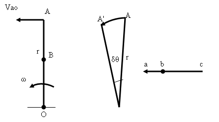
Fig. 3.1 motion of a link
Velocity of A relative to O = Arc AA'/ δt
\[{V_{ao}} = r\frac{{\delta \theta }}{{\delta t}}\]
In the limits, when δt tends to zero
\[{V_{ao}} = r\frac{{d\theta }}{{dt}}\]
\[{{\text{V}}_{{\text{ao}}}} = {\text{ r }} \times \omega {\text{ }}\left( {{\text{OA }} \times \omega } \right)\]
The direction of Vao is along the displacement of A. Also, as δt approaches zero, AA’ will be perpendicular to OA. Thus, velocity of A is ωr and perpendicular to OA. It is so because A can neither approach nor recede from O and thus, the only possible motion of A relative to O is in a direction perpendicular to OA.
Now, consider appoint B o the link OA
The velocity of point B = ω OB which is perpendicular to OB
If ob represents the velocity of B, it can be found that
\[\frac{{{\text{ob}}}}{{{\text{oa}}}} = \frac{{{\text{ }}\omega {\text{OB}}}}{{\omega {\text{ OA}}}} = \frac{{{\text{OB}}}}{{{\text{OA}}}}\]
The important conclusion here is that b divides the velocity vector in the same ratio as B divides the link. The velocity vector Vao gives the velocity of A at a particular instant of time at other instant of time when OA takes other position the velocity vector will change its direction accordingly.
5.3 FOUR BAR MECHANISM ANALYSIS BY RELATIVE VELOCITY METHOD
Four bar mechanism is given below in the diagram having angular velocity ω rad/s in the clockwise direction
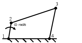
Fig. 3.2 four bar mechanism
Velocity of the point 3 relative to 1= velocity of point 3 relative to velocity of point 2+ velocity of point 2 relative to velocity of point 1.
\[{{\text{V}}_{{\text{31}}}} = {{\text{V}}_{{\text{32}}}} + {{\text{V}}_{{\text{21}}}}\]
The velocity of point 3 relative to 1 will be equal to velocity of point 3 relative to 4 as point 1 & point 4 both are fixed point, so we can write
\[{{\text{V}}_{{\text{34}}}} = {{\text{V}}_{{\text{32}}}}{\text{ + }}{{\text{V}}_{{\text{21}}}}\]
Here
\[{{\text{V}}_{{\text{21}}}} = \omega\times {\text{12}}\], which is perpendicular to 12
Similarly,
V32 is unknown in magnitude but it will be perpendicular to link 23
V34 is unknown in magnitude but it will be perpendicular to link 43
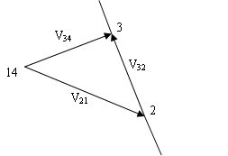
Fig. 3.3
Angular velocity of links
a. Velocity of 3 relative to 2, V32 link 3 moves in anti-clockwise about 2.
\[{{\text{V}}_{{\text{32}}}}{\text{ = }}{\omega _{{\text{32}}}} \times {\text{23}}\]
\[{\omega _{{\text{32}}}} = {\text{ }}\frac{{{{\text{V}}_{{\text{32}}}}}}{{{\text{23}}}}\]
b. Velocity of link 34
Angular velocity of link 3 relative to 4 is in clockwise direction & is given by
\[{\omega _{{\text{34}}}}{\text{ = }}\frac{{{{\text{V}}_{{\text{34}}}}}}{{{\text{43}}}}\]
5.4 VELOCITY OF RUBBING AT PINS
Two links forms a turning pairs at points 1, 2, 3&4 as shown in figure 3.4. It can be seen here that a pin forms an integral part of a link and this pin fits into the hole in the other link which permits the relative motion between them. When two links are connected then the surface at the hole of one link rubs against the surface of pin of the other link. The rubbing velocity between the two links depends on the angular velocity of one link relative to the angular velocity of the other.
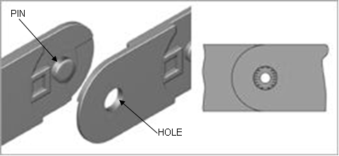 Fig.3.4 two links joined by pins
This can be explained at the points 1, 2, 3 & 4 in figure 3.2 of the four bar mechanism.
At pin 1
The pin at 1 connects links 12 and 41, the velocity of rubbing will depend only on links 12 as 41 is the fixed link.
Let \[{r_1}\] = radius of the pin at point 1
Then the velocity of rubbing = \[{r_1} = \omega \]
At pin 2
\[{\omega _{21}} = {\omega _{12}} = \omega \] clockwise
\[{\omega _{23}} = {\omega _{32}} = \frac{{{V_{23}}}}{{23}}\] counter clockwise
The direction of the two angular velocities of the links 12 and 23 are in opposite directions, the angular velocity of one link relative to the other is the sum of the two velocities.
Let \[{r_2}\] = radius of the pin at point 2
Then the velocity of rubbing = \[{r_2} = \left( {{\omega _{12}} + {\omega _{23}}} \right)\]
At pin 3
\[{\omega _{23}} = {\omega _{32}}\] counter clockwise
\[{\omega _{41}} = {\omega _{34}}\] clockwise
Let \[{r_3}\] = radius of the pin at point 3
Then the velocity of rubbing = \[{r_3} = \left( {{\omega _{23}} + {\omega _{43}}} \right)\]
At pin 4
Let \[{r_4}\] = radius of the pin at point 4
Then the velocity of rubbing = \[{r_4} = {\omega _{34}}\]
Last modified: Tuesday, 25 March 2014, 9:08 AM