Site pages
Current course
Participants
General
Module 1. Introduction to Theory of Machine
Module 2. Planar Mechanism
Module 3. Velocity and Acceleration Analysis
15 March - 21 March
22 March - 28 March
29 March - 4 April
5 April - 11 April
12 April - 18 April
19 April - 25 April
26 April - 2 May
Lesson 15.
15.1 INTRODUCTION
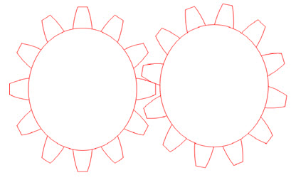
Power can be transmitted in number of ways i.e by belts, rops, chains and couplings but gears form very important part of power transmission. With the help of gears definite velocity ratio is achieved and they found applications in many machines such as transmission of automobiles, machine tools, rolling mills, and clocks. A gear is a toothed circular part which mesh with another toothed part to provide specific output. The output may be in the form of speed or torque. The purpose of projections or teeth is to reduce slipping. Two or more gears working together is called a gear train. Intermeshing gears always turn in counter directions.

Fig.4.1 Meshing of two gears
Gears of different sizes can be combined together to design different mechanisms depending upon particular requirement. The gears are generally designed to prevent failure against static and dynamic loads. Gears can be made from cast iron, steel, bronze, phenolic resin, nylon and Teflon etc. The major advantages of gear drives include transmission of exact velocity ratio, high efficiency and compact layout.
15.2 HISTORY OF GEARS
Gears are as old as any other machinery, the mankind is using. The early Greeks and Romans made considerable use of gears. The Antikythera mechanism is an example of an ancient geared device, that was designed to calculate astronomical positions (built between 150 and 100 BC). The first known geared mill was built about 27 B.C. In the fourth century, BC Aristotle wrote about wheels using friction between smooth surfaces to transmit motion.
Early man used wooden gears to grind wheat and hammer metals. During the beginning of the Christian era gears were used in many machines such as clocks, waterwheels and windmills. Philon of Byzantium, Archimedes, Dionysius of Alexandria and Leonardo da Vinci have made use of gears in various machines.
15.3 GEAR CLASSIFICATION
The gears may be classified into three types as discussed below:
1. According to relative position of shafts: The shafts between which motion has to be transmitted may be
Parallel
Intersecting
Non-intersecting and Non-parallel
2. DEPENDING UPON THE PERIPHERAL VELOCITY
a) When the velocity of gears is less than 3m/s, the gears are termed as Low Velocity Gears.
b) When the velocity of gears is between 3m/s to 15 m/s, the gears are termed as Medium Velocity Gears.
c) When the velocity of gears is greater than 15m/s, they are termed as high velocity gears.
3. According to contact of Gears:
It may be classified as
i) External Gearing
ii) Internal Gearing
In External Gearing the gears mesh externally while in internal gearing the gears mesh internally with each other.
15..3.1 Parallel Shafts
The following are the main types of gears connecting parallel shafts.
1. Spur Gear
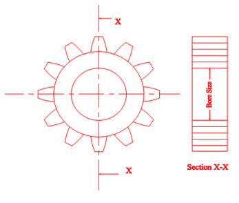
The teeth of spur gears are straight and run parallel to the axis of the shaft.
 Fig.4.2 Spur gear
Spur gears may have external or internal contact depending on the type of layout. They are the most common type of gear and are quite simple to manufacture. Spur gears are mainly used in tractor transmissions, blenders, clothes dryers, and flour mills.