Site pages
Current course
Participants
General
Module 1. Introduction to Theory of Machine
Module 2. Planar Mechanism
Module 3. Velocity and Acceleration Analysis
15 March - 21 March
22 March - 28 March
29 March - 4 April
5 April - 11 April
12 April - 18 April
19 April - 25 April
26 April - 2 May
Lesson 18.
18.1 According to fundamental law of gearing, if the gears have meshed properly, the line of action should be straight and pass through the Pitch Point of the gears. Two tooth profiles that satisfy the above condition and used extensively in gear manufacturing process are involute and cycloidal profiles. An involute curve can be imagined as it is traced by a point on a stretched string during its unwinding from a cylinder. Whereas when two generating circles roll on the pitch circle they trace the cycloidal tooth profile. Involute profiles have constant pressure angle, are easy and cheap to manufacture but cycloidal profile tooth have variable pressure angle, more precise to manufacture so are relatively costlier than involute profiles. Pressure angle is necessary for quiet operation of gears. In cycloidal gears, the pressure angle is maximum at the start and end of engagement and is zero at pitch point. So the running of cycloidal gears is little noisy. But at the same time cycloidal gears are more robust due to wider flanks. Exact center distance has to be maintained in cycloidal gears while in the involute gears the center distance of mounting shafts can be varied by adding correction factor.
18.2 GEAR TRAINS
When two or more gears mesh it is called a gear train. Gears mesh with each other to transmit rotational motion from one shaft to another. There is a driver gear and a driven gear and the gear ratio produced by the train depends on the number of teeth on each gear. As already described the meshing gears rotate in opposite directions and in order to have the same direction of rotation of the driver gear and the driven gear an idler gear is added between the driver and driven gears.
18.3 VELOCITY RATIO
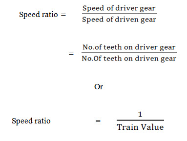
Velocity ratio of gear train is defined as the ratio of the speed of the driver gear to the speed of the driven gear and the ratio of speed of two meshing gears varies inversely as the number of teeth.
