Site pages
Current course
Participants
General
Module 1. Perspective on Soil and Water Conservation
Module 2. Pre-requisites for Soil and Water Conse...
Module 3. Design of Permanent Gully Control Struct...
Module 4. Water Storage Structures
Module 5. Trenching and Diversion Structures
Module 6. Cost Estimation
Lesson 7. Runoff Measurement using Weirs
7.1 Introduction
Runoff information is needed for design of various soil and water conservation structures. In the previous lectures (5 and 6), peak runoff rate as well as runoff volume estimations are discussed. Runoff is estimated because it is not always possible to obtain field measured data, which is costly and time consuming. However, there are many methods of runoff measurements. In field, it is generally carried out using current meters and calibrated or rated channel cross sections. The flumes or standardized weirs, together with water level readings or automatic recorders are also used. In this lesson only weirs will be discussed.
7.2 Weirs
Weirs consisting of a barrier are dam structures of known hydraulic specifications, placed across the stream to constrict the flow, and allow the water to flow over a crest. It is a calibrated instrument used to measure the flow in an open channel, or the discharge of a well or a canal outlet at the source.Weir openings may be rectangular, trapezoidal, or triangular in cross section. The basic formula for calculating discharge through a weir is
![]()
Where Qis the discharge over weir, C isthe coefficient dependent on the nature of crest and approach conditions, L is the length of crest, H is the head of crest, m is an exponent depending upon the weir opening.
7.3 Classification of Weirs
Weirs are classified based on the shape of their opening or notch. The edge of the opening can be either sharp or broad-crested.
7.3.1 Broad-Crested Weirs
A weir that has a horizontal or nearly horizontal crest sufficiently long in the direction of the flow so that the nappe will be supported and hydrostatic pressures will be fully developed for at least a short distance. Broad crested weir is shown in Fig. 7.1.
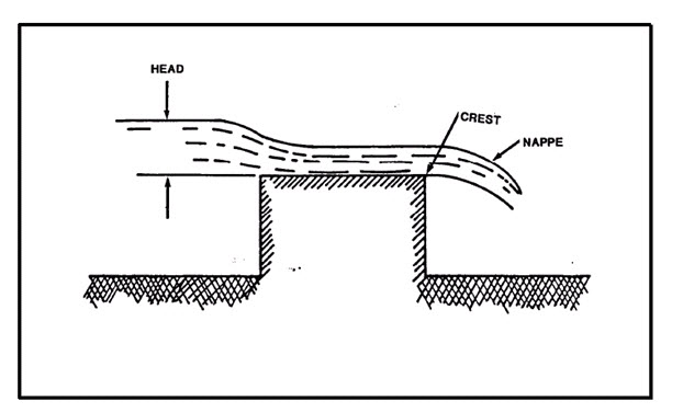
Fig. 7.1 Broad crested weir.
(Source: http://navalfacilities.tpub.com/mo221/mo2210113.htm, accessed on Aug 14, 2013)
Broad crested weirs are recommended to overcome the difficulty of maintaining the sharp edge of weirs under field conditions for longer periods. Its discharge depends upon the shape of the weir and the crest, which define the nappe characteristics. Eqns. (2) and (3) represent the general formula for determination of maximum discharge considering the velocity approach and without velocity approach respectively

![]()
Where Qmax is the maximum discharge over the weir, Cdis the coefficient of discharge, L is the length of the weir, H is the head of water above the crest, Hvis the velocity head, H1is the total head (H1= H+ Hv) and V is the velocity of flow over the weir.
Example 7.1: Determine the maximum discharge over a broad-crested weir 60 meters long having 0.6 m height of water above its crest. Take coefficient of discharge as 0.595. Also determine the new discharge over the weir, considering the velocity of approach. The channel at the upstream side of the weir has a cross-sectional area of 45 sq meters.
Solution:
Given, L = 60 m; H = 0.6 m; Cd = 0.595; A = 45 m2
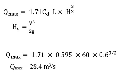
Maximum discharge over the weir without considering the velocity of approach
We know that the maximum discharge over the weir,
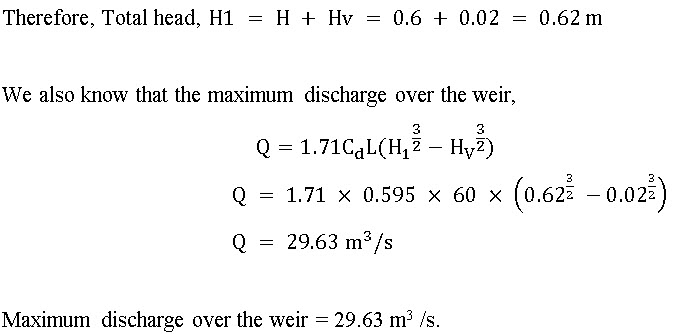
Maximum discharge over the weir considering the velocity of approach
We know that velocity of approach,

and the head due to velocity of approach,

7.3.2 Sharp-Crested Weir
These are generally used for water measurement on the farm or small streams. These can be of three types based on the shape of notch. These are
Rectangular Weir
Cipoletti Weir or Trapezoidal Weir
V Notch Weirs or Triangular Weir
The commonly used terms with sharp created weirs are shown in Fig. 7.2.
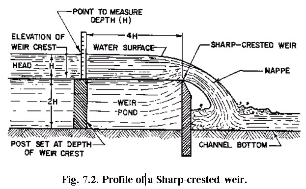
(Source: http://www.flowmeterdirectory.com/flowmeter_artc_02021403.html accessed on July 28, 2013)
7.3.2.1 Rectangular Weirs
Rectangular weir takes its name from the shape of its notch. The discharge through a weir or notch is directly related to the water depth (H), (Fig.7.3) and H is known as the head. This head is affected by the condition of the crest, the contraction, the velocity of approaching stream and the elevation of the water surface downstream from the weir. Rectangular weirs can be suppressed, partially contracted, or fully contracted.
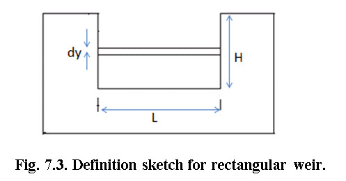
Considering theFig.7.4, discharge through the rectangular weir is calculated as
Q = 0.0184LH3/2 (7.4)
For one side contraction Q = 0.0184 (L0.1H) (7.5)
For both side contraction Q= 0.0184(L0.2H) (7.6)
Example 7.2: Water flows through a contracted rectangular weir 120 cm long to a depth of 30 cm, it then flows along a rectangular channel 150 cm wide and over a second weir which has length equal to the width of the channel. Determine the depth of water over the second weir.
Solution:
The first weir is contracted, i.e. both end contracted.
Given, Length of the weir (L) = 120 cm
Depth of water over the weir (H) = 30 cm

= 344.67 liters/sec
In second weir, length of the weir (L) =150 cm
Discharge through first weir and second weir is same.
Let assume, depth of water over second weir is = H cm
Now,
![]()
344.67 = 0.0184×150×H3/2
H= 24.97 cm. Ans.
So, the depth of water over the second weiris 24.97 cm.
7.3.2.1.1 Suppressed Rectangular Weir
A rectangular weir whose notch or opening sides are coincident with the sides of the approached rectangular channel and extend unchanged downstream from the weir. The weir goes across the entire channel width for a suppressed rectangular, sharp-crested weir. Fig. 7.4 (a) and (b) shows suppressed and contracted rectangular weirs.
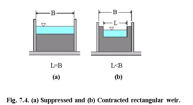
(Source:http://www.brighthubengineering.com/hydraulics-civil- engineering/88804-calculations-for-rectangular-weir-flow-equations/, accessed on Aug 14, 2013)
7.3.2.1.2 Contracted Rectangular Weir
A contracted rectangular sharp-crested weir, as shown in Fig. 7.4(b) has weir length less than the width of the channel. This type of rectangular weir is sometimes called an unsuppressed rectangular weir. The sides and crest of a weir are far away from the sides and bottom of the approach channel. The nappe will fully contract laterally at the ends and vertically at the crest of the weir.
7.3.2.2 Cipoletti Weirs
The Cipolletti weir (Fig. 7.5) is trapezoidal in shape. The slope of the sides, inclined outwardly from the crest, should be one horizontal to four vertical. The selected length of notch (L) should be at least 3H and preferably 4H or longer. Cipoletti weirs are considered fully contracted.
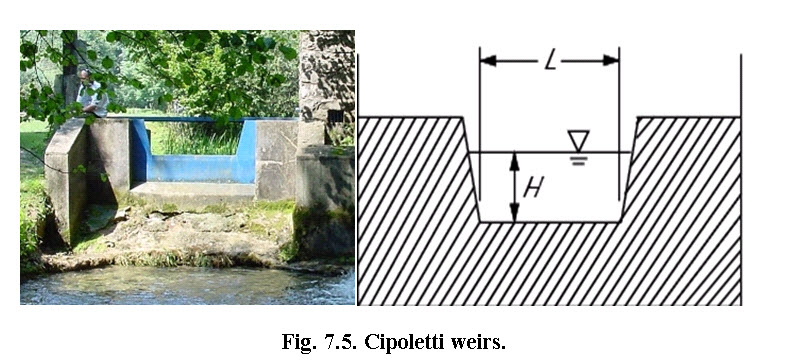
(Source: https://www.codecogs.com/users/23547/cipolettiweir.png, accessed on Aug 14, 2013)
Discharge through Cipoletti weir is computed by the following formula:
![]()
Example7.3: A Cipoletti weir has a breadth of 60 cm at its crest. The head of water flowing over the crest is 30 cm. Determine its discharge.
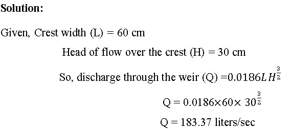
Discharge of Cipoletti weir is 183.37 litres/sec. Ans.
7.3.2.3 V- Notch Weir
A V-notch weir (sometimes called a triangular weir) is shown in Fig. 7.6. This weir is especially good for measuring low flow rates. The flow area decreases as H increases, so a reasonable head is developed even ata very small flow rate. Depth of water above the bottom of the V is called head (H). Its design causes small changes in discharge hence causing a large change in depth and thus allowing more accurate measurement than with a rectangular weir. Head (H) should be measured at a distance of at least 4H upstream of the weir.
The most common weirs are 90° weirs, for larger flow measurements, and 45° weirs for medium-range flow measurements. Sometimes, 60° weirs are used for intermediate to larger flows, and 30° or 22.5° weirs are used for very small flows.
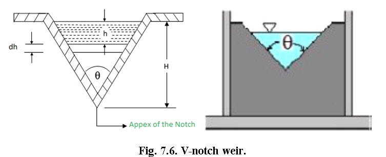
(Source: https://www.codecogs.com/users/23547/vnotchweir.png, accessed on Aug 14, 2013)
Considering the Fig. 7.6, the discharge over a V-Notch sharp-crested weir is calculated as

Where, 
If Θ=900 ![]()
For Θ=900, H in cm and Q in litres/sec

In SI units: 
Where Q is the discharge over weir (m3/sec), Cd is the Coefficient of discharge, θis the angle of notch (degrees) and H is the head above bottom of notch (m).
Example7.4: Determine discharge of 90o V-notch having 30 cm head of flow.
Solution:
Discharge through V-notch Q=0.0138
Q = 0.0138
Q = 68.02litres/sec
So, discharge through 90o V-notch having 30 cm head of flow is 68.02litres/sec.
Sharp crested weirs may also be classified as suppressed and contracted.
7.4 Operation of Weirs
Properly constructed and installed weirs provide most accurate flow measurement. However, improper setting and operation may result in large errors in the discharge measurements. To ensure reliable results in measurement, the following precautions are necessary in the use of weirs.
The weirs should be set at lower end of a long pool sufficiently wide and deep having smooth flow at velocities less than 15cm/sec.
Baffles may be put in weir pond to reduce velocity.
The weir wall must be vertical.
The center line of the weir should be parallel to the direction of flow.
The crest of weir should be level so that water passing over it will be of the samedepth at all points along the crest.
Notch should be of regular shape and its edge must be rigid and straight.
The weir crest should be above the bottom of the approach channel.
The crest of weir should be placed high enough so that water will fall freely below weir.
The depth of water flow over the rectangular weir should not less than about 5 cm and not more than about 2/3 crest width.
The scale or gauge used for measuring the head should be located at a distance of about four times the approximate head. Zero of scale should be exactly at the same level as the crest level of the weir.
7.5 Limitations of Weirs
Weirs are not always suitable for measuring flow. Sufficient head is required for operating any type of weir.
They are not accurate unless proper conditions are maintained.
They require a considerable loss of head which is mostly not available in channels on flat gradients.
Weirs are not suitable for water carrying silt.
Weirs are not easily combined with turnout structures.
Reference
Das, G. (2012). Hydrology and Soil Conservation Engineering, Prentice Hall of India Private Ltd., New Delhi, India.
Michael, A.M. and Ojha, T.P. (2006). Principles of Agricultural Engineering, Vol. II, Jain Brothers, New Delhi, India.
Schwab, G.O. Fangmeier, D.D. Elliot, W.T. Frevert, R.K. (1993). Soil and Water Conservation Engineering, John Wiley & Sons, New York, United States.
Internet references
http://www.brighthubengineering.com/hydraulics-civil-engineering/88804-calculations-for-rectangular-weir-flow-equations/, accessed on Aug 14, 2013
http://www.fao.org/docrep/v5400e/v5400e0b.htm accessed on Aug 14, 2013
http://www.flowmeterdirectory.com/flowmeter_artc_02021403.html, accessed on July 28, 2013
http://navalfacilities.tpub.com/mo221/mo2210113.htm, accessed on Aug 14, 2013
http://www.usbr.gov/pmts/hydraulics_lab/pubs/wmm/chap08_10.html accessed on Aug 14, 2013
http://www.usbr.gov/pmts/hydraulics_lab/pubs/wmm/index.htmaccessed on Aug 14, 2013
Suggested Readings
Bansal, R. K. (2005). Fluid Mechanics and Hydraulic Machines, Laxmi Publications (P) Ltd., New Delhi, India.
Clemmens, A.J. Wahl, T.L. Bos, M.G. Replogle J.A. (2001). Water Measurement with Flumes and Weirs, Publication 58, ISBN 90-70754-55-X, ILRI, Wageningen, The Netherland.