Site pages
Current course
Participants
General
Module 1. Perspective on Soil and Water Conservation
Module 2. Pre-requisites for Soil and Water Conse...
Module 3. Design of Permanent Gully Control Struct...
Module 4. Water Storage Structures
Module 5. Trenching and Diversion Structures
Module 6. Cost Estimation
Lesson 10 Energy and Momentum Equation
This chapter deals with three equations commonly used in fluid mechanics and soil and water conservation: the conservation of mass, conservation of energy, and conservation of momentum. These equations have great importance in hydraulic structure design, soil and water conservation structures design, canal simulations, irrigation systems design etc. We now give a brief description of the conservation of mass, energy and momentum equations.
Conservation of Mass – This principle says that the mass neither be created nor destroyed. This forms the basis for continuity equation
Conservation of Energy – this principle says that the energy neither be created nor destroyed, only can change the form. This principle forms the basis for energy equation
Conservation of Linear Momentum – The interaction of force and time acting on the object is equal to the change in momentum of the object.
10.1 Mass in Open Channel Flow
The conservation of mass or continuous steady flow is expressed mathematically in the basic continuity equation as:
![]()
Where, Q is the discharge, in![]() ;A is the cross-sectional area, in and V is the average channel velocity, in m/sec.
;A is the cross-sectional area, in and V is the average channel velocity, in m/sec.
10.2 Energy in Open Channel Flow
The total energy head at a point in an open channel is the sum of the potential and kinetic energy of the flowing water. The energy per unit weight is the sum of pressure head or static head, velocity head or kinetic head and potential head. For steady irrotational flow these sum are constant. These explained by the following equation.
Equation 2is commonly known as Bernoulli’s equation. The term ![]() is pressure head, ratio of pressure
is pressure head, ratio of pressure ![]() and specific weight (w);
and specific weight (w); ![]() is kinetic head proportional to square of velocity (v), and z is the potential head. All term has the units in m.
is kinetic head proportional to square of velocity (v), and z is the potential head. All term has the units in m.
As per Bernoulli’s principle, the total energy in steady, irrotational flow is constant at any point, thus
If a tube with a 90 degree elbow is inserted into the flow with the open end pointing into the flow, then the water level will rise to a level higher than the water surface elevation in the channel, and this distance is a measure of ability of the water velocity to do work. Newton’s laws of motion can be used to determine that this distance is ![]() , where g is the acceleration due to gravity. Therefore the total energy head at a point in an open channel is.
, where g is the acceleration due to gravity. Therefore the total energy head at a point in an open channel is.![]()
A longitudinal profile of total energy head elevations is called the energy grade line. The longitudinal profile of water surface elevations is called the hydraulic grade line. The energy and hydraulic grade lines for uniform open channel flow are illustrated in figure10.1. For flow to occur in an open channel, the energy grade line must have a negative slope in the direction of flow. A gradual decrease in the energy grade line for a given length of channel represents the loss of energy caused by friction. When considered together, the hydraulic and energy grade lines reflect not only the loss of energy by friction, but also the conversion between potential and kinetic forms of energy.
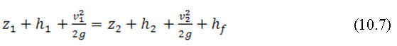
As water flows down a channel, the flow loses energy because of friction and turbulence. The total energy head between two points in a channel reach can be set equal to one another if the losses between the sections are added to the downstream total energy head. This equality is commonly known as the Energy Equation, which is calculated as:
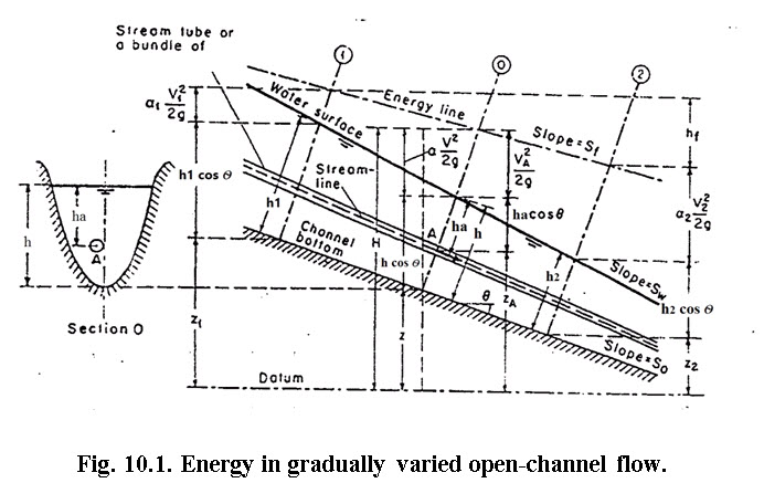
(Source: http://www.most.gov.mm/techuni/media/CE_04016_chap2.pdf)
Total energy at section -1
Applying energy principle to section 1 and 2 we have.
 Where,
![]() = friction loss between section 1 and 2.
= friction loss between section 1 and 2.
If the bed slope of the channel is small; i.e., Θ= 0

If ![]() (uniform velocity distribution)
(uniform velocity distribution)
 Where,
![]() are depth of open channel flow at channel sections 1 and 2respectively, in m;
are depth of open channel flow at channel sections 1 and 2respectively, in m;![]() = are average channel velocities at channel sections 1 and 2 respectively, in m/sec;
= are average channel velocities at channel sections 1 and 2 respectively, in m/sec; ![]() = are channel elevations above an arbitrary datum at channel sections 1 and2, respectively, in m;hf =is the head or energy loss betweenchannelsections1and2inm; Θ is the bed slope of the channel; g is the acceleration due to gravity, 9.8.
= are channel elevations above an arbitrary datum at channel sections 1 and2, respectively, in m;hf =is the head or energy loss betweenchannelsections1and2inm; Θ is the bed slope of the channel; g is the acceleration due to gravity, 9.8.![]()
The above equation is same as the well-known Bernoulli’s equation.
10.3 Momentum Equation in Open Channel Flow
According to Newton's Second Law of Motion, the change of momentum per unit of time is equal to the result ant of all external forces applied to the moving body. Application of this principle to open channel flow produces a relationship which is virtually the same as the Energy Equation expressed in equation 10.7.
The momentum of the flow passing the channel section per unit time is expressed as
Momentum =, ![]()
Where Β is the momentum coefficient, Υ is the unit weight of water, Q is the discharge, and is V the mean velocity.
Applying the momentum principle for the momentum change per unit time in the body of water enclosed between section 1 and 2 may be written:
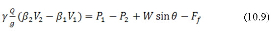
Where, p1 and p2 are the resultants of pressure acting on two sections; W is the weight of water enclosed between section 1 and 2; Ff is the total external force of friction and resistant action along the surface of contact between the water and the channel.
The slope of the channel is assumed relatively small. Thus, in the short reach of a rectangular channel of small slope and width
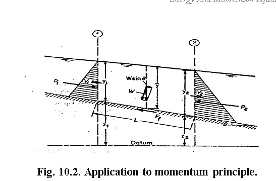
Fig. 10.2. Application to momentum principle.
(Source: http://www.most.gov.mm/techuni/media/CE_04016_chap2.pdf).
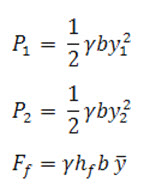

Substituting all the above expression for the corresponding items in Equation (10.9) and simplifying,
![]()
Where, is the Losses due to external forces exerted on water by the walls of the channel. This equation appears to be practically same as the energy equation (10.7).
References
Bansal, R. K. (2009). Fluid Mechanics and Hydraulic Machines, Laxmi Publications (P) Ltd, New Delhi, pp. 771-774.
Office of Design. (2009). Drainage Handbook Open Channel. Drainage Section Tallahassee, Florida.
Internet References
http://www.most.gov.mm/techuni/media/CE_04016_chap2.pdf
http://www.tandfonline.com/doi/pdf/10.1080/00221680009498340
http://nptel.iitm.ac.in/courses/IIT-MADRAS/Hydraulics/pdfs/Unit6/6_3.pdf
http://nptel.iitm.ac.in/courses/105107059/module4/lecture7/lecture7.pdf
Suggested Readings
Bansal, R. K. (2009). Fluid Mechanics and Hydraulic Machines, Laxmi Publications (P) Ltd, New Delhi, pp. 771-774.
Modi, P. N., Seth, S. M. (1989). Hydraulics and Fluid Mechanics (including Hydraulic Machines).Standard Book House, Delhi.
http://www.most.gov.mm/techuni/media/CE_04016_chap2.pdf
http://www.tandfonline.com/doi/pdf/10.1080/00221680009498340
http://nptel.iitm.ac.in/courses/IIT-MADRAS/Hydraulics/pdfs/Unit6/6_3.pdf
http://nptel.iitm.ac.in/courses/105107059/module4/lecture7/lecture7.pdf
Last modified: Saturday, 1 February 2014, 10:09 AM