Site pages
Current course
Participants
General
Module 1. Perspective on Soil and Water Conservation
Module 2. Pre-requisites for Soil and Water Conse...
Module 3. Design of Permanent Gully Control Struct...
Module 4. Water Storage Structures
Module 5. Trenching and Diversion Structures
Module 6. Cost Estimation
Lesson 12. Hydraulic Jump or Standing Wave
Hydraulic jump defined as, the rise of water level, which takes place due to the transformation of unstable shooting flow (super-critical) to the stable streaming flow (sub-critical flow).It frequently occurs in a canal below a regulating sluice, at the toe of a spillway, at downstream of narrow channel or at the place where a steep channel slope suddenly turns flat.
Hydraulic jump defined as, the rise of water level, which takes place due to the transformation of unstable shooting flow (super-critical) to the stable streaming flow (sub-critical flow).
It frequently occurs in a canal below a regulating sluice, at the toe of a spillway, at downstream of narrow channel or at the place where a steep channel slope suddenly turns flat.
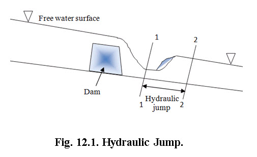
Consider the flow of water over a dam as shown in Fig. 12.1. The depth of water at the section 1-1 is small, but it increases towards downstream rapidly over a short length of the channel. This is because at the section 1-1, the flow is a shooting flow as the depth of water at section 1-1 is less than the critical depth. Shooting flow is an unstable type of flow and does not continue on the downstream side. Then this shooting will convert itself into a streaming or tranquil flow and hence depth of water will increase. This sudden increased of depth of water is called a hydraulic jump or a standing wave.
When hydraulic jump take place, a loss of energy due to eddy formation and turbulence occurs.
12.1 Expression for Depth of Hydraulic Jump
Following assumption are made before deriving the expression for the depth of hydraulic jump,
Flow is uniform and pressure distribution is due to hydrostatic before and after the jump.
Losses due to friction on the surface of the bed of the channel are negligible
The slope of the bed of the channel is small, so that the component of the weight of the fluid in the direction of flow is negligibly small.
Consider a hydraulic jump formed in a channel of horizontal bed as shown in figure 12.2.
Consider there are two sections 1-1 and 2-2 before and after hydraulic jump.
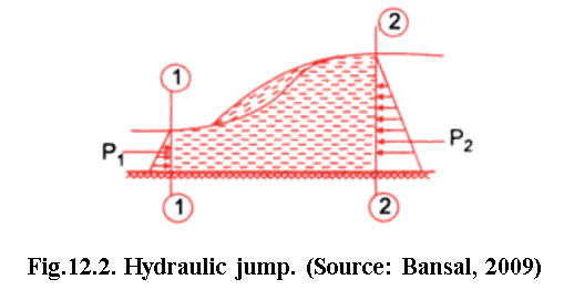 Let d1 is the depth of flow at section 1-1 i.e. initial depth;d2 is the depth of flow at section 2-2 i.e. depth of flow after the hydraulic jump, also known as sequent depth or theoretical tail water depth. The depth pair at section 1-1 and 2-2 are called conjugate depth.
v2is thevelocity of flow at section 1-1;v2 is the velocity of flow at section 2-2;z1 is the depth of centroid of area at section 1-1 below free surface; z2 is the depth of centroid of area at section 2-2 below free surface;A1 is the cross sectional area at section 1-1;A2 is the cross sectional area at section 2-2.
Consider unit width of the channel.
The force acting on the mass of water between sections 1-1 and 2-2 are:
(i) Pressure force P1 and P2 on section 1-1 and 2-2 respectively.
(ii) Frictional force on the floor of the channel, which assumed to be negligible.
Let q = discharge per unit width
![]()
Now, pressure force on section 1-1


Similarly pressure force on section 2-2

Net force acting on the mass of water between section 1-1 and 2-2

But from the momentum principle, the net force acting on a mass of fluid must be equal to the rate of change of momentum in the same section.
Rate of change of momentum in the direction of force


Change of velocity in the direction of force v1 - v2
Hence, rate of change of momentum in the direction of force
![]()
Hence, according to the momentum principle, the expression given by eq. (12.2) is equal to the expression given by eq. (12.3)
or 
But from equation (1), ![]()
Substituting the value of and in eq. (12.4) and by solving we get,

Multiplying both sides by d2 , we get


By solving eq. (12.6) we get

Neglecting the negative sign, we get
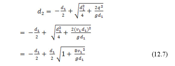
Now, depth of hydraulic jump = (d2-d1)
Froude number on the upstream side is given by
Substituting the value in equation (12.7) we get,

12.2 Energy Dissipation due to Hydraulic Jump
When hydraulic jump take place, a loss of energy due to eddies formation and turbulence occurs. This loss of energy is equal to the difference of specific energies at sec. 1-1 and 2-2.
Let E1, and E2 are the energy at section 1-1 and 2-2 respectively. Loss of energy due to hydraulic jump


But from eq. (5),
Substituting the value of in eq. (12.9) and solving the expression, we get

12.3 Jump Efficiency
The ratio of specific energy after the jump (E2) to the energy before the jump (E1) is defined as the efficiency of the jump,
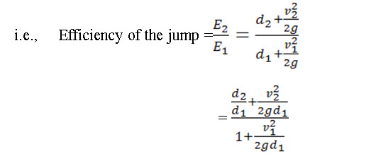

Eq. (12.11) indicates that the jump efficiency is a dimensionless function of Froude number fr1 before the jump.
12.4 Relative Loss of Energy
Relative loss of energy is the ratio of loss of energy due to hydraulic jump to the specific energy prior to hydraulic jump, it can be written as,
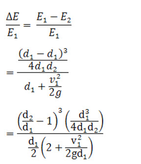
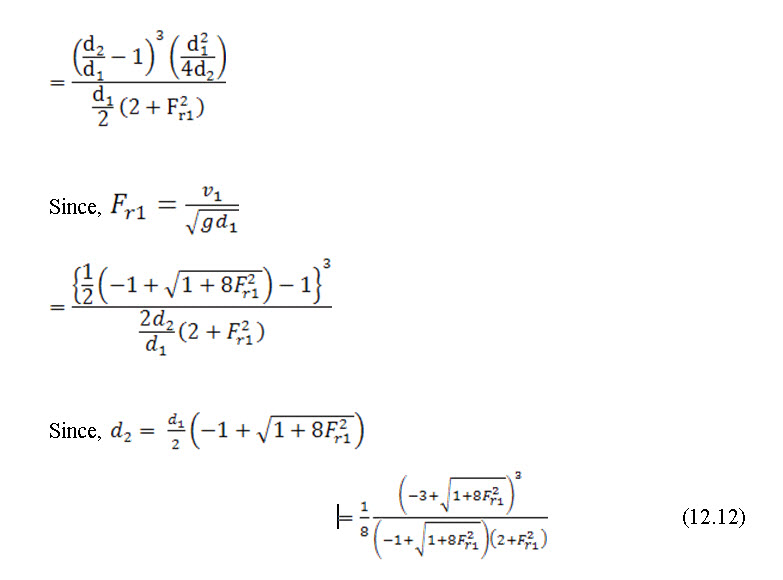
Equation (12) gives the relative energy loss equation in hydraulic jump
12.5 Types of Hydraulic Jump
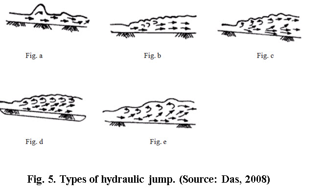
Several distinct types of hydraulic jump in a horizontal floor are classified, mainly on the basis of Froude number and shape of the water surface formed in the jump zone. According to the study of USBR (United States Bureau of Reclamation), these types are called;
(i) Undular jump: It occurs in the range of from 1 to 1.7. Water surface shows undulations (figure 12.3a). Here efficiency is very small, is also small.
(ii) Weak jump: A series of small rollers develop on the surface of the jump, but downstream water surface remains smooth (figure 12.3b). Velocity throughout is fairly uniform and energy loss is low. Efficiency varies from 15 to 18%. varies from 1.7 to 2.5. Therefore, this jump is called weak jump.
(iii) Oscillating jump: There is an oscillating jet entering the jump bottom to surface and back again with no periodicity. Each oscillation produces a large wave of irregular period which, very commonly in canals, can travel for kilometres doing unlimited damage to earthen banks and ripraps (figure12.3c). varies from 2.5 to 4.5. Here efficiency is about 45%.
(iv) Steady jump: Here varies from 4.5 to 9. Efficiency or energy dissipation varies from 45% to 70%. The jump is well balanced and performance is at the best (figure 12.3d).
(v) Strong jump: It occurs when > 9. It is rough jump, but effective since energy dissipation may reach from 70% to 85% (figure 12.3e).
Solved Examples:
Problem 12.1: Find the depth of flow of water after the hydraulic jump in a rectangular channel of 4 m width having a discharge of 16 m3/s. The depth of water in the channel before hydraulic jump was 0.5 m.
Solution:
Width of channel, b = 4 m; Depth of flow before jump, d1 = 0.5 m; Discharge, Q = 16 m3/s.
Let the depth of flow after hydraulic jump is d2, hence from eq. (12.8)
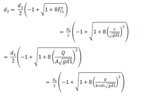
Now, substituting the values of Q, b,d1 and g we get,
d2 =2.316m Ans.
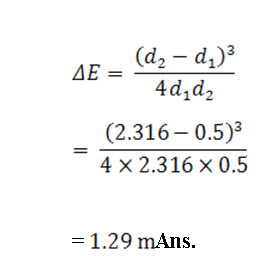
Problem 12.2. Determine the energy loss after the hydraulic jump for the previous problem.
Solution:
From eq. (12.10) the energy loss due to hydraulic jump is given by,
Reference
Bansal, R. K. (2009). Fluid Mechanics and Hydraulic Machines, LaxmiPublications (P) Ltd, New Delhi, pp. 777-781.
Das, M. (2008). Open Channel Flow, Prentice Hall of India Pvt. Ltd., New Delhi.
Das, M. (2008). Fluid Mechanics and Turbomachines, Prentice Hall of India Pvt. Ltd., New Delhi, pp. 226.
Internet References
http://nptel.iitm.ac.in/courses/IIT-MADRAS/Hydraulics/pdfs/Unit28/28_1.pdf
http://nptel.iitm.ac.in/courses/IIT-MADRAS/Hydraulics/pdfs/Unit29/29_1.pdf
http://nptel.iitm.ac.in/courses/IIT-MADRAS/Hydraulics/pdfs/Unit31/31_1.pdf
Suggested Readings
Bansal, R. K. (2009). Fluid Mechanics and Hydraulic Machines, Laxmi Publications (P) Ltd, New Delhi, pp. 777-781.
Das, M. (2008). Open Channel Flow, Prentice Hall of India Pvt. Ltd., New Delhi.
http://nptel.iitm.ac.in/courses/IIT-MADRAS/Hydraulics/pdfs/Unit31/31_1.pdf