Site pages
Current course
Participants
General
MODULE 1.
MODULE 2.
MODULE 3.
MODULE 4.
MODULE 5.
MODULE 6.
MODULE 7.
MODULE 8.
MODULE 9.
MODULE 10.
MODULE 11.
MODULE 12.
LESSON 25. Design of One Way Slabs
25.1 INTRODUCTION
For small spans say up to 3.75 m in width, which are not subjected to heavy loadings, a simple slab may suffice. When the ratio of the length of a room to its breadth is greater than 2, most of the load is carried by the short span (i.e., the width the room) and as such the slab is designed to span along the width of the room as a one way slab. In case of one-way slab, the main reinforcement of the slab, span along the width of the room while the distribution bars, laid at right angles to the main reinforcement, lie parallel to the length of the room. If the length to breadth ratio of the room is less than 2, the slab is designed as a two-way reinforced slab. In case of two-way slab main reinforcements are provided both along the length as well as along the width of the room. Depending upon the building plan, or the arrangement of main beams and/or secondary beams, the slab may have only one span, or it may be continuous over several supports.
The maximum bending moment for which the slab should be designed varies with the nature of the slab (whether one-way reinforced or two-way reinforced), loading conditions, the number of spans and the end-conditions of the slab. The bending moment which causes tension at the bottom of the slab, usually near the centre of the span, is called positive or sagging bending moment and the bending moment which causes tension at the top of the slab, usually over the supports, is called negative or hogging bending moment. Thus, for positive bending moment the main reinforcement is placed near the bottom face of the slab while for negative bending moment, the main reinforcement is placed near the top face of the slab.
25.2 LOADING ON SLABS
Loading on slabs may be in the form of uniformly distributed loads or concentrated loads or combination of the two. The slab in residential or public building or other similar structures are mostly subjected to uniformly distributed loads only. Slabs in bridges, culverts, or in other similar situations are subjected to the concentrated load on account of vehicles or trains passing over the slab. Thus, the loading on a slab normally consists of:
(a) Live loads.
(b) External dead load. (Finishing and Partitions etc.).
(c) Dead load of the slab itself.
Live loads and external dead loads may be given or these may be calculated with the help of given data, while the dead load due to self-weight of the slab has to be calculated after deciding the probable thickness of the slab vide Basic-Rule at Art. 24.3.
25.3 ARRANGEMENT OF REINFORCEMENTS IN SLABS
A standard bar bending arrangement of the designed reinforcement for a one-way slab and for a continuous slab has been shown in Fig 25.1 and Fig. 25.2 respectively.
25.4. STEPS TO BE FOLLOWED IN THE DESIGN OF ONE-WAY REINFORCED SLAB
Whatever may be the width of the slabs it should always be designed for a width of equal to one metre and the same design should be adopted for the rest of the slab. The design procedure for a uniformly loaded one-way reinforced slab can be divided in the following steps.
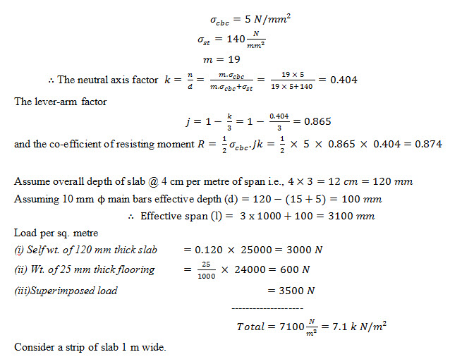
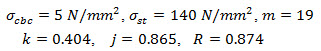
(1) Calculate values of the design constants i.e. k (neutral axis factor), j(lever arm factor) and R (moment of resistance factor) from the given stresses in concrete and steel reinforcement.
For
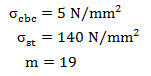
The value of design constants workout to
k = 0.404
j = 0.865
and R = 0.874
(2) Assume suitable thickness or depth (D) of the slab for working out its self-weight. As a guide for total loads up to 7kN/m2, assume slab thickness @ 40 mm/m when MS reinforcement ( σst =140 N/ ) is to be adopted and @ 45 to 50 mm/m when HYSD reinforcement ( σst =230 N/ ) is to be adopted. For higher values of total load the thickness of the slab to be assumed should be increased suitably.
(3) Calculate effective span for the slab vide basic rule at Art.24.2.
(4) (i) Calculate wd – total dead load including self wt. of slab, wt. of finishing (flooring, terracing, ceiling plaster etc.) and other fixed type of imposed loads (if any).
(ii) Calculate -total live load and any other not fixed type of imposed load.
Total load for design of slab or w = wd + ws .
(5) Calculate maximum bending moment (M) by the governing formula vide basic rule ar Art. 24.12.
(6) Calculate effective depth of the slab by considering max. B.M. anywhere in the slab by the formula.

Where b = 100mm
(7) Select suitable diameter ( Φ ) of the main bars and fix the value of overall depth (D) of the slab.
As per rule at Art. 24.6. (ii) it should be ensured that the dia. of bar is not more than th of the total thickness of the slab. If the value of overall depth(D) of the slab works out to be nearly equal to or less than the depth assumed in step(2) proceed further with the design. If on the other hand the value of (D) work out to be appreciably greater than that assumed in step (2) recalculate the self wt. of slab on the basic of revised depth [this should be taken slightly more than that worked out in step (6)] and revise the design.
(8) Calculate area of main reinforcement by the formula ![]()
(9) Calculate centre to centre spacing of main bars by the formula ![]()
where
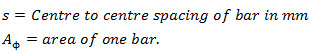
Ensure that maximum spacing adopted in design should not exceed 3d or 400 mm whichever is smaller.
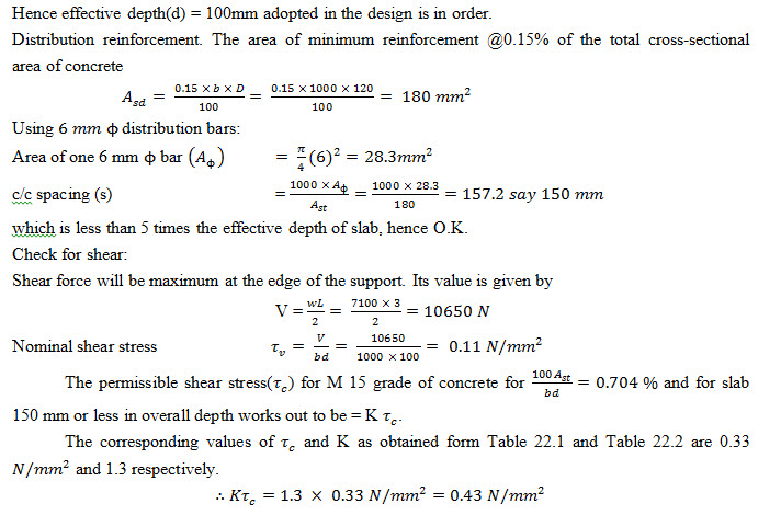
(10) Calculate area of distribution reinforcement at the rate of 0.15% of the total cross sectional area in case MS bars are used as reinforcement. In case HYSD bars or welded wire fabrics are used, the value can be reduced to 0.12%.
(11) Select suitable diameter of distribution bars and find centre to centre spacing of bars as per step (9) above.
(12) Give check for required effective depth of slab from stiffness/deflection control consideration by following the steps given below.
(i) Calculate (p) the percentage of tension reinforcement provided ![]()
(ii) Calculate value of modification factor (M.F.) corresponding to value of (p) calculated in step (i) above from graph in Fig. 24.1.
(iii) Calculate required effective depth (d) from stiffness/deflection control consideration. For a simply supported slab ![]()
This should work out to be less than the value of effective depth adopted in design.
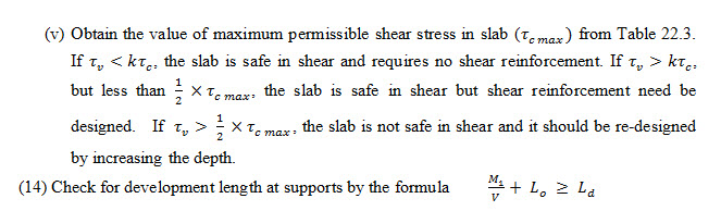
(13) Give check for shear by following the steps given below.
(i) Calculate max. shear force(V) from the governing formula vide basic rule at Art. 24.13.
(ii) Calculate nominal shear stress by the formula ![]()
(iii) Calculate form Table 22.1 value of permissible shear stress ( Tc ) for the given grade of concrete for percentage of reinforcement provided.
(iv) Obtain value of k from Table 22.2 and work out value of permissible shear stress in slab by the formula Tc = kTc
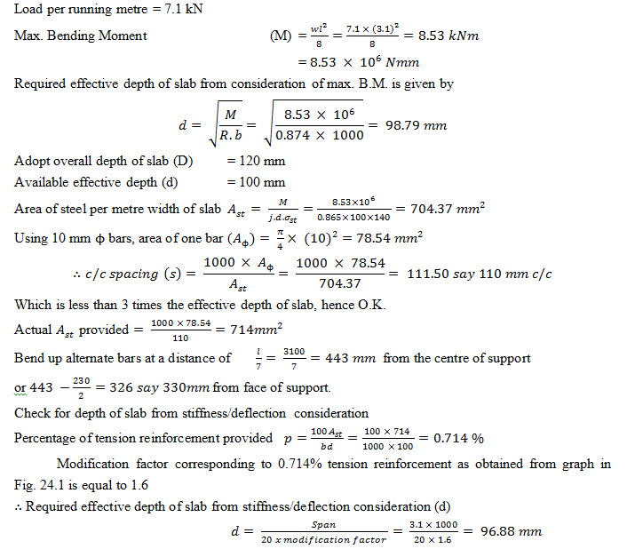
Example 25.1 Design a floor slab simply supported over a clear span of 3m. The slab is to be finished with 25 mm thick cement concrete flooring. The superimposed load on the slab is to be 3500 N per square metre. The bearing of the slab on the supporting walls may be taken as 230 mm. Adopt M 15 grade of concrete and mild steel reinforcement.
Solution Design constants. From the given data
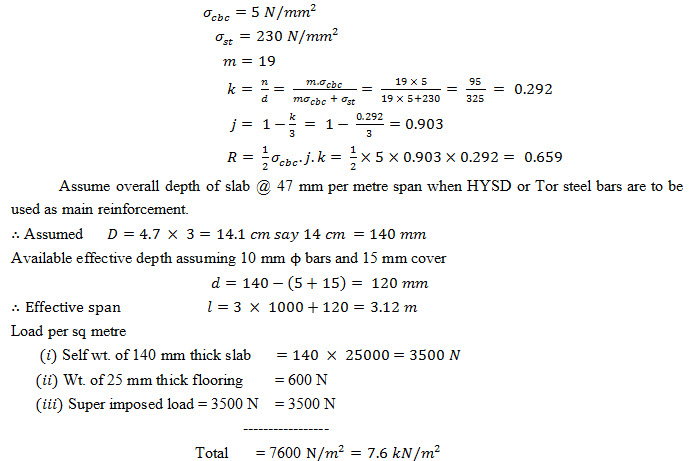
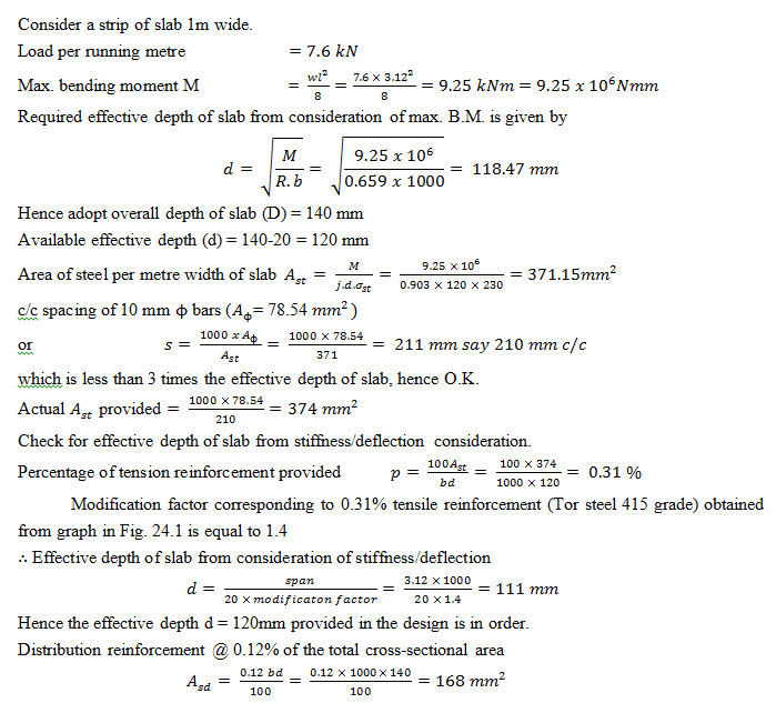
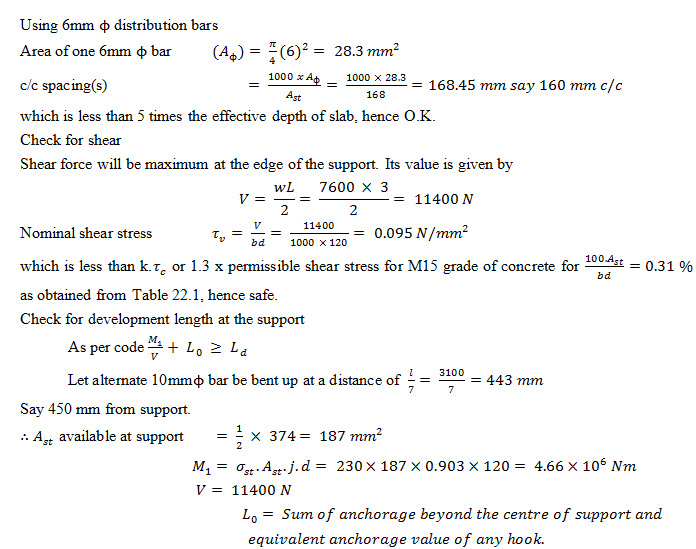
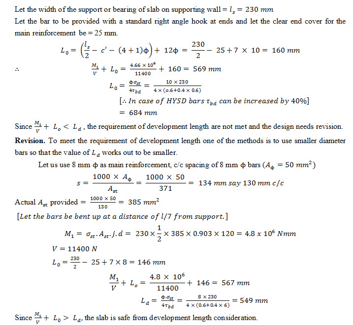
Example 25.2 Design the floor slab in example using high yield strength deformed bars (HYSD) or tor-steel as main reinforcement instead of mild steel reinforcement. The other data remaining same.
Solution Design constants. From given data
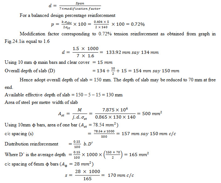
Example 25.3 Design a cantilever slab to carry a superimposed load of . The overhang of the slab is 1.5 m. Adopt M 15 grade of concrete and mild steel reinforcement.
Solution Design constant : From the given data
Load per sq meter : Assume an average thickness of slab = 120 mm
(i) Self wt. of 120 mm thick slab = 0.12 * 25000 = 3000 N
(ii) Superimposed load = 4000 N
---------------
Total = 7000 N/m2 = 7 kN / m2
Consider a strip of slab 1m inside
Load per running metre (w) = 7kN
Max Bending moment ![]()
Required effective depth of slab from B.M. consideration
![]()
Required effective depth of slab from consideration of stiffness/deflection : From stiffness/deflection consideration, effective depth (d) is given by relation.
Check for shear :
Max. shear force V = wl = 7 x 1.5 = 10.5 kN
![]()
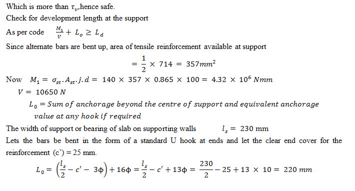
Check for development length : The 10 mm main bar must be extended into the support for distance
= Ld = 58.3 Φ = 58.3 * 10 = 583 mm
The designed floor slab is shown in Fig. 25.4.
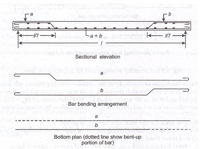
Fig. 25.1 Bar bending arrangement for a one-way slab
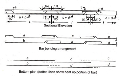
Fig. 25.2 Bar bending arrangement for a continuous slab
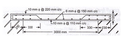
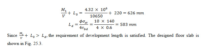
Fig. 25.3 Bar bending arrangement (Example 25.1)
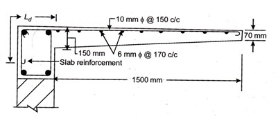
Fig. 25.4 Section of slab showing details of reinforcement (Example 25.3)
Last modified: Friday, 28 March 2014, 11:32 AM