Site pages
Current course
Participants
General
MODULE 1.
MODULE 2.
MODULE 3.
MODULE 4.
MODULE 5.
MODULE 6.
MODULE 7.
MODULE 8.
MODULE 9.
MODULE 10.
MODULE 11.
MODULE 12.
LESSON 27. Design of Lintel with Sunshade
27.1 INTRODUCTION
A lintel may be defined as a beam provided over an opening for door, window, cupboard etc., in a wall. It serves to bridge the gap of the opening and it permits the construction of wall above. The magnitude of load (due to structure above) carried by the lintel depends upon the location of the opening in the wall and the height of the wall above the opening. Normally the spans for door or windows are small and the height of wall between the lintel and floor/roof slab is adequate and the lintels may be subjected to only the load due to the wall above. However when the height of the wall above the lintel is inadequate, it may also be subjected to the loads due to floor or roof slab besides the weight of masonry above. The computation of load for the design of lintel can be broadly divided in the following five categories.
Case 1. When the length of wall on either side of the opening is more than half the effective span of the lintel.
Case 2. When the length of wall on one side of the opening is less than half the effective span of the lintel.
Case 3. When the length of wall on both side of the opening is less than half the effective span of lintel.
Case 4. When the wall above the lintel has openings.
Case 5. When a slab transfers load to lintel.
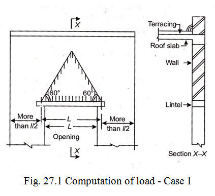
Case 1. When the length of wall on either side of the opening is more than half the effective span of the lintel:
In this case it is assumed that because of the arch action developed within the masonry above the opening, only the weight of masonry contained in an equilateral triangle (having base length equal to the effective span l) is transferred on the lintel. This is shown in Fig. 27.1. The load due to weight of masonry and the slab etc. outside the equilateral triangle or dispersion triangle are assumed to be dispersed to the walls on either side of the opening and are not transferred to the lintel.
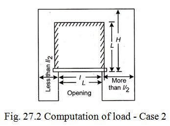
Case 2. When the length of wall on one side of the opening is less than half the effective span of the lintel.
When the location of the opening is close to an end will such that the length of wall on one side of the opening is less than half the effective span of the lintel, the load transferred to the lintel is taken equal to the weight of masonry contained in a rectangle of height equal to the effective span (l). This shown in Fig. 27.2.
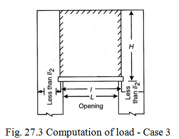
Case 3.When the length of wall on both sides of the opening is less than half the effective span of lintel.
When both ends of the opening are close to end walls, so that the length of wall on each side of opening is less than half the effective span of the lintel, the load transferred to the lintel is taken equal to the weight of masonry contained in a rectangle having width equal to the effective span and height equal to the full height (H) of the wall. This is shown in Fig. 27.3.
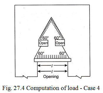
Case 4. When the wall above the lintel has openings.
If the wall above the lintel has openings for ventilators etc. and such openings are so located as to intersect the sides of the dispersion triangle, in such cases, the load transferred to the lintel is taken equal to the weight of the masonry contained in the area formed by drawing the dispersion lines at 60˚ from the top edges of the openings. This is shown in Fig. 27.4.
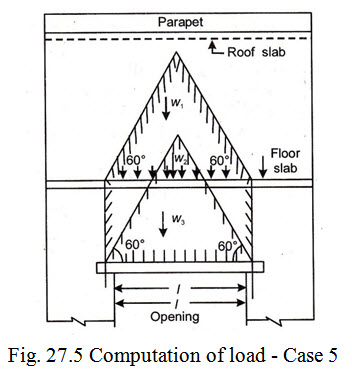
Case 5. When a slab transfers load to lintel.
If the wall above the lintel supports a floor or roof slab at a height more than the height of the dispersion triangle, the load transferred on the lintel shall be worked out as per details in Case 1. If the level of the floor/roof slab is such that distance between the top of lintel and the slab works out to be less than the height of the dispersion triangle, in such a case, the load transferred to the lintel from the structure above the opening will comprise of the following.
(i) The load (W1) equal to the weight of masonry contained in the rectangle of height equal to the height of the slab above the lintel and base width equal to the effective span of lintel.
(ii) The load (W2) equal to design load of slab
(iii) The load (W3) equal to the weight of masonry contained in the equilateral triangle (with length = l) above the floor slab.
This is shown in Fig. 27.5.
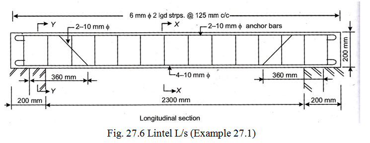
Example 27.1 Design a reinforced concrete lintel over a show case window opening 2.3 metre wide. The window is to be centrally located in 230 mm thick brick wall. The height of the brick work above the lintel may be taken as 2m. A 600 mm wide sun shade is required to be cast monolithic with the lintel. Design the sun shade as well. Adopt M 15 grade of concrete and mild steel reinforcement.
Solution Design constant :
For \[{\sigma _{cbc}} = 5N/m{m^2}\]
\[m = 19\]
and \[{\sigma _{st}} = 140N/m{m^2}\]
Therefore, \[k = 0.404\] , \[j = 0.865\] , \[R = 0.874\]
In order to calculate the load transferred by the sun shade to the lintel, it is necessary to design the sun shade first.
1. Design of sun shade : Assume that thickness of sun shade slab to be = 70 mm.
Loads per metre run consist of :
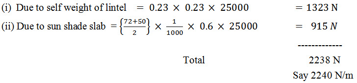
(i) Due to self weight = 0.070 x 25000 = 1750 N
(ii) Live load etc. = 1000 N
-----------
Total 2750 N/m
Max. B.M. = \[\frac{{w{l^2}}}{2} = 2750x\frac{{{{0.6}^2}}}{2}Nm = 0.495x{10^6}Nmm\]
\[d = \sqrt {\frac{{0.495x{{10}^6}}}{{0.874x1000}}}= 23.79mm\]
Effective depth(d) from stiffness/deflection consideration:
For a balanced design, percentage reinforcement is given by
\[p = \frac{{k.{\sigma _{cbc}}}}{{2{\sigma _{st}}}} \times 100 = \frac{{0.404 \times 5}}{{2x140}} \times 100 = 0.72\]
Modification factor corresponding to 0.72% reinforcement as obtained from graph in Fig. 24.1 is equal to 1.6. Therefore required effective depth of the cantilever sun shade slab from stiffness/deflection consideration is given by
\[d = \frac{L}{{7 \times Modificationfactor}} = \frac{{600}}{{7 \times 1.6}} = 53.57mm\]
Assuming 6 mm \[\phi \] main bars, overall depth
\[D = 53.57 + 15 + \frac{6}{2} = 71.57say72mm\]
Available effective depth \[= 72 - 15 - \frac{6}{2} = 54mm\]
\[{A_{st}} = \frac{M}{{j.d.{\sigma _{st}}}} = \frac{{0.495 \times {{10}^6}}}{{0.865 \times 54 \times 140}} = 75.69m{m^2}\]
Distribution reinforcement: Magnitude of minimum reinforcement or distribution reinforcement anywhere in the slab is given by
\[{A_{sd}} = \frac{{0.15 \times b \times D}}{{100}}\]
Assuming the slab to be tapered to 50 mm at free end.
Average overall depth of slab \[= \frac{{72 + 50}}{2} = 61mm\]
\[{A_{sd}} = \frac{{0.15 \times 1000 \times 61}}{{100}} = 91.5m{m^2}\]
c/c spacing of 6 mm \[\phi \] bars
\[\left[ {{A_\phi } = \frac{\pi }{4}{{\left( 6 \right)}^2} = 28m{m^2}} \right]\]
\[= \frac{{1000}}{{91.5}} \times 28\]
\[= 306mmc/c\]
However as per rule
c/c spacing of 6 mm main bars will be restricted to
\[= 3 \times d = 3 \times 54 = 162mmsay150mmc/c\]
and c/c spacing of 6 \[\phi \] mm distribution bar \[= 5 \times d = 5 \times 54 = 270mmsay200mmc/c\]
2. Design of lintel. Assume the size of the lintel as 230 mm wide x 230 mm deep.
Let the bearing of the lintel on the end supports = 200 mm
Therefore,effective span = 2.3 + 0.20 = 2.5 m
Design loads for Lintel:
(a) To calculate load due to triangular portion of the brickwork.
Height of triangle having a base length of 2.5m and base angle of 60˚ each
\[= \sqrt 3\times \frac{{2.5}}{2} = 2.165m\]
Load due to triangular portion of the brickwork.
Or \[W = \frac{1}{2}x2.5x2.165x0.23x19200 = 11951N\]
(b) Uniformly distributed load (w) for design consist of the following:
Max. Bending moment \[M = \frac{{Wl}}{6} + \frac{{w{l^2}}}{8}\]
\[= \frac{{11951 \times 2.5}}{6} + \frac{{2240 \times {{2.5}^2}}}{8}\]
\[= 4980 + 1750 = 6730Nm = 6.73x{10^6}Nmm\]
Required effective depth \[d = \sqrt {\frac{M}{{R.b}}}= \sqrt {\frac{{6.73 \times {{10}^6}}}{{0.874 \times 230}}}= 182mm\]
Assuming 10 \[\phi \] mm main bars, and clear cover of 20 mm, overall depth
\[D = {\text{}}182{\text{}} + {\text{}}20{\text{}} + {\text{}}\frac{{10}}{2} = 207mmsay200mm\]
Available effective depth \[= 200 - \left( {20 + \frac{{10}}{2}} \right) = 175mm\]
Area of steel required \[{A_{st}} = \frac{M}{{j.d.{\sigma _{st}}}} = \frac{{6.73 \times {{10}^6}}}{{0.865 \times 175 \times 140}} = 317m{m^2}\]
No. of 10 mm \[\phi \] bars out of 4 bars are bent up near support at
\[\left[ {{A_\phi } = \frac{\pi }{4}{{\left( {10} \right)}^2} = 79m{m^2}} \right]\]
\[= \frac{{317}}{{79}} = 4Nos.\]
Minimum reinforcement: Minimum reinforcement ( As ) required for the lintel is given by the relation \[\frac{{{A_s}}}{{bd}} = \frac{{0.85}}{{{f_y}}}\]
Taking \[{f_y} = 250N/m{m^2}\]
\[{A_s} = \frac{{0.85 \times 230 \times 175}}{{250}} = 137m{m^2}\]
Since \[{A_{st}} > {A_s}\] , hence safe.
Check for depth from stiffness/deflection consideration:
\[p = \frac{{100{A_{st}}}}{{bd}} = \frac{{100 \times 4 \times 79}}{{230 \times 175}} = 0.79\]
Modification factor corresponding to 0.79% tensile reinforcement as obtained from graph in Fig 24.1 is equal to 1.56
Required effective depth of lintel from stiffness/deflection considerations
\[d = \frac{L}{{20 \times Modificationfactor}}= \frac{{2.3 \times 1000}}{{20 \times 1.56}} = 74mm\]
Which is less than 175 mm, hence safe.
Adopted depth is O.K.
Check for shear : Shear force (V) will be maximum at the edge of the wall support. Its value is given by
\[V = \frac{W}{2} + \frac{{wL}}{2} = \frac{{11951}}{2} + \frac{{2240 \times 2.3}}{2}\]
\[= 5975.5 + 2576 = 8551.5N = 8552Nsay\]
Nominal shear stress \[{\tau _v} = \frac{V}{{bd}}\]
\[{\tau _v} = \frac{{8552}}{{230 \times 175}} = 0.21N/m{m^2}\]
Assuming 2 Nos. 10mm \[\phi\] bars out of 4 bars are bent up near support at
\[\frac{l}{7} = \frac{{2.5}}{7} = 0.357m\] say 360 mm from supports
Area of tensile reinforcement available near support \[= 2 \times 79m{m^2} = 158m{m^2}\]
\[p = \frac{{100{A_s}}}{{bd}} = \frac{{100 \times 158}}{{230 \times 175}} = 0.39\]
From Table 22.1 value of permissible shear stress \[({\tau _c})\] for M 15 grade of concrete and even 0.25% reinforcement is \[= 0.22N/m{m^2}\] , which is more than \[{\tau _v}\] \[(0.21N/m{m^2})\] and hence no shear reinforcement need be designed. Thus only minimum shear reinforcement will be provided.
Minimum shear reinforcement : Centre to centre spacing of vertical stirrups to meet the requirements of minimum shear reinforcement is given by
\[{S_v} = \frac{{2.5{A_{sv}}.{f_y}}}{b}\]
Using 6mm\[\phi\] 2 legged vertical stirrups
\[{A_{sv}} = 2 \times \frac{\pi }{4}{\left( 6 \right)^2} = 57m{m^2}\]
\[{S_v} = \frac{{2.5 \times 57 \times 250}}{{230}} = 155mm\]
Maximum spacing of shear reinforcement: Maximum c/c spacing of stirrups should not exceed least of following values
\[\left( i \right)0.75d = 0.75x175 = 125mm\]
\[\left( {ii} \right)450mm\]
\[\left( {iii} \right){s_v} = 155mm\]
Hence provide 6 mm \[\phi\] 2 legged stirrups @ 125 mm c/c throughout the length of the beam. Provided 2-10mm \[\phi\] anchor bars.
Check for development length at supports:
Since 2 – 10 mm \[\phi\] bars are available at supports as tensile reinforcement
\[{A_{st}} = 2 \times 79m{m^2}\]
\[{M_1} = {\sigma _{st}}.{A_{st}}.j.d\]
\[= 140 \times 2 \times 79 \times 0.865 \times 175\]
\[= 3.348 \times {10^6}Nmm\]
\[V = 8552N\]
\[{L_0} = \frac{{{l_s}}}{2} - c' + 13\phi\]
\[= \frac{{200}}{2} - 25 + 13 \times 10\]
\[= 205mm\]
\[\frac{{{M_1}}}{V} + {L_0} = \frac{{3.348 \times {{10}^6}}}{{8552}} + 205\]
\[= 392 + 205 = 597mm\]
\[{L_d} = \frac{{\phi {{\text{\sigma }}_{{\text{st}}}}{\text{}}}}{{4{\tau _{bd}}}}\]
\[= \frac{{10{\text{x}}140{\text{}}}}{{4x0.6}}\]
\[= 583mm\]
Since \[\frac{{{M_1}}}{V} + {L_0} = {L_d}\] , hence O.K.
Last modified: Saturday, 29 March 2014, 4:33 AM