Site pages
Current course
Participants
General
MODULE 1.
MODULE 2.
MODULE 3.
MODULE 4.
MODULE 5.
MODULE 6.
MODULE 7.
MODULE 8.
MODULE 9.
MODULE 10.
MODULE 11.
MODULE 12.
LESSON 28. Axially Loaded RCC Columns
28.1 INTRODUCTION
A reinforced concrete column is said to be subjected to an axial load when the line of the resultant thrust of loads supported by the column is coincident with the line of C.G. of the column in the longitudinal direction. Depending upon the architectural requirements and the loads to be supported, R.C. Columns may be cast in various shapes i.e., square, rectangular, hexagonal, octagonal or circular. Columns of ell-shape or tee-shape are also sometimes used in multi-storeyed buildings. The longitudinal bars in columns help to bear the load in combination with the concrete. These bars are uniformly spaced along the perimeter of the columns as near the surface as permissible. The longitudinal bars are held in position by transverse reinforcement, or lateral binders. The binders prevent displacement of the longitudinal bars during concreting operation and also check the tendency of their buckling outwards under loads.
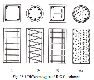
The transverse reinforcement or binders are of two types. Type (1) consists of separate small diameter steel binder bent around the longitudinal bars. The diameter, centre to centre spacing and the arrangement of the separate binder, depends upon the number and diameter of longitudinal bars and the size of the column. In the second type, reinforcing bar forming the tie, is wound round the longitudinal bars in the form of a closely spaced continuous helix and is termed as spiral or helical reinforcement. The helical reinforcement in addition to rendering support to longitudinal bars against buckling and displacement, also act to confine the concrete within it in the form of a core thereby increasing the load carrying capacity of the column.
Different arrangement of separate binders and helical reinforcement are shown in Fig. 28.1. The load carrying capacity of a column depends upon number of variables. The following points should be kept in view while designing a column to effect saving in cost.
-
Column with separate lateral ties works out to be cheaper than columns with spiral reinforcement.
-
Axially loaded columns with a low percentage of steel works out to be more economical per tonne of load supported than columns with a higher percentage of steel.
-
The richer the concrete, the more economical is the design.
28.2 TYPES OF COLUMNS
Columns can be broadly divided into the following three categories:
(i) Columns reinforced with longitudinal steel and lateral ties or binders.
(ii) Columns reinforced with longitudinal steel and closely spaced spirals.
(iii) Composite columns in which steel or cast iron structural member is encased in a concrete column of the type (i) or (ii) referred above.
(iv) Concrete filled steel pipe columns.
Out of the above types, columns reinforced with longitudinal steel and lateral ties or spirals are most common in use. The columns of type (iii) are recommended when the loads to be carried are extremely heavy and the dimensions of the columns are to be restricted from architectural considerations. Columns of type (iv) are used where loads to be carried are light and it is essential to provide smallest possible diameter of the column from aesthetic reasons.
28.3 EFFECTIVE LENGTH OF A COLUMN
From practical considerations the actual length (L) of a column is taken as the clear distance between the floor and the lower extremity of the capital, drop panel or slab whichever is smaller while in a beam and slab construction the actual length (L) is taken as the clear distance between the floor and the underside of the shallower beam framing into the column in each direction at the next higher floor level.
The effective length of a column depends upon the conditions of its end. For the purpose of design, only the effective length of a column is considered. Table 28.1 gives the effective length \[({l_{ef}})\] of a column is terms of unsupported length (l) for various end conditions.
TABLE 28.1 Effective length of compression members (as per IS : 456-1978)
|
|
Degree of end restraint of compression member |
Theoretical value of effective length |
Recommended value of effective length |
|
1. |
Effectively held in position and restrained against rotation at both ends. |
0.50 l |
0.65 l |
|
2. |
Effectively held is position at both ends, restrained against rotation at one end. |
0.70 l |
0.80 l |
|
3. |
Effectively held in position at both ends but not restrained against rotation |
1.00 l |
1.00 l |
|
4. |
Effectively held in position and restrained against rotation at one end and at the other restrained against rotation but not held in position. |
1.00 l |
1.20 l |
|
5. |
Effectively held in position and restrained against rotation at one end and at the other partially restrained against rotation but not held in position. |
--- |
1.50 l |
|
6. |
Effectively held in position at one end but not restrained against rotation and at the other end restrained against rotation but not held in position. |
2.00 l |
2.00 l |
|
7. |
Effectively held in position and restrained against rotation as one end but not held in position nor restrained against rotation at the other end. |
2.00 l |
2.00 l |
Note. l is the unsupported length of compression member.
28.4 LONG AND SHORT COLUMNS
In general columns may be divided in two different categories namely (i) short columns and (ii) long columns. A column is considered to be short when the ratio of its effective length to its least lateral dimensions does not exceed 12. If the ratio of the effective length to its least lateral dimension exceeds 12, the column is considered to be a long column.
Since a long slender column buckles more easily, the ratio between the column’s effective length and its least lateral dimension have definite relation with the load carrying capacity of the column. On account of its buckling tendency a long column has less strength than a short column of the same sectional area and hence can carry lesser loads as compared to short column.
Thus in long columns the maximum permissible stresses in concrete and steel are reduced by multiplying the respective stresses by a reduction coefficient \[{C_r}\] given by the formula
\[{C_r} = 1.25 - \frac{{{l_{ef}}}}{{48b}}\] … (i)
where
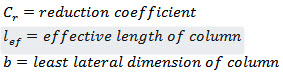
Note. In case of columns having helical binders, (where permissible load is based on the area of concrete core) the least lateral dimension should be taken as the diameter of the concrete core.
Hence, the safe load that a long column can carry is obtained by multiplying the value of load which a short column of the same sectional area can carry by the reduction coefficient \[{C_r}\] . For more exact calculations, the maximum permissible stresses in a reinforced concrete column or part thereof having a ratio of effective column length to least lateral radius of gyration above 40 shall not exceed those which result from the multiplication of the appropriate maximum permissible stress in concrete and steel reinforcement by the co-efficient given by the formula
\[{C_r} = 1.25 - \frac{{{l_{ef}}}}{{160.{i_{min}}}}\]
where \[{i_{min}}\] is the least radius of gyration.
28.5 PERMISSIBLE STRESSES IN R.C. COLUMNS
As a result of experiments all the codes recommend reduction of stresses in concrete in direct compression as well as steel reinforcement in R.C. columns. As per revised IS : 456 – 1978, the permissible stresses for various grades of concrete and for various type of steel reinforcement to be considered in the design of column are reproduced below.
(a) Permissible stress in concrete:
|
|
Permissible stress in compression |
|
|
(Bending) \[{\sigma _{cbc}}\] |
(Direct) \[{\sigma _{st}}\] |
|
|
M 10 |
3.0 \[N/m{m^2}\] |
2.5 \[N/m{m^2}\] |
|
M 15 |
3.0 \[N/m{m^2}\] |
2.5 \[N/m{m^2}\] |
|
M 20 |
7.0 \[N/m{m^2}\] |
5.0 \[N/m{m^2}\] |
|
M 25 |
8.5 \[N/m{m^2}\] |
6.0 \[N/m{m^2}\] |
|
M 30 |
10.0 \[N/m{m^2}\] |
8.0 \[N/m{m^2}\] |
(b) Permissible stress in steel reinforcement : For column bars in compression ( \[{\sigma _{sc}}\] )
\[= 130N/m{m^2}forMSbars\]
\[= 190N/m{m^2}forHYSDbars\]
28.6 LOAD CARRYING CAPACITY OF DIFFERENT TYPES OF SHORT COLUMNS
The safe axial load carrying capacity of different types of short columns shall be as given below.
28.6.1 Short Columns and Pedestals with Lateral Ties
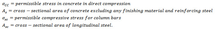
The permissible axial load (P) on a short column or pedestal reinforced with longitudinal bars and lateral ties is given by the equation \[P = {\sigma _{CC}}.{A_c} + {\sigma _{sc}}.{A_{sc}}\]
Where
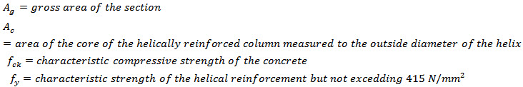
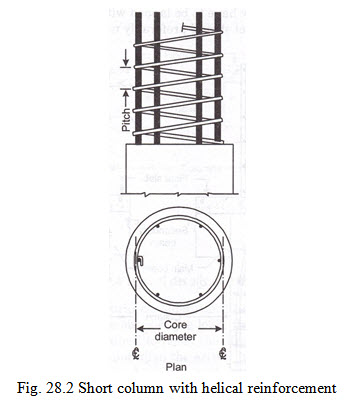
28.6.2 Short Columns with Helical Reinforcement
Fig. 28.2 shows the short column with helical reinforcement. The permissible load for columns with helical reinforcement shall be 1.05 times the permissible load for similar member with lateral ties or rings. This provision can be made applicable only if the ratio of volume of helical reinforcement to the volume of core is not less than
\[0.36\left( {\frac{{{A_g}}}{{{A_c}}} - 1} \right)\frac{{{f_{ck}}}}{{{f_y}}}\]
where
28.6.3 Composite Columns
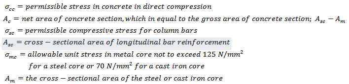
The allowable axial load P on a composite column consisting of structural steel or cast-iron column thoroughly encased in concrete reinforced with both longitudinal and spiral reinforcement shall not exceed that given by the following formula
\[P = {\sigma _{CC}}.{A_c} + {\sigma _{sc}}.{A_{sc}} + {\sigma _{mc}}.{A_m}\]
Where
28.7 BASIC RULES FOR THE DESIGN OF COLUMNS (AS PER IS : 456-1978)
Longitudinal reinforcement:
(i) The cross-sectional area of longitudal reinforcement in a column shall not be less than 0.8% and not more than 6% of the gross cross-sectional area of the column. In places where bars from a column below have to be lapped with those in the column to be provided above, the maximum percentage of steel should preferably not exceed 4%.
The object of fixing the upper limit of 6% is to avoid such a concentration of steel as would create problems in placing and consolidation of concrete. In normal case, the designer should attempt to restrict the percentage of steel in a column to 4%.
(ii) The minimum number of longitudinal bars provided in a column shall be four in rectangular columns and six in circular columns.
(iii) A column having helical binders must have at least six bars of longitudinal reinforcement within the helical reinforcement.
(iv) The minimum diameter of the longitudinal bars shall not be less than 12 mm and the maximum diameter should preferably not exceed 50 mm.
(v) The minimum cover to the outside of longitudinal bars shall be 40 mm or the diameter of the bar whichever is more. In case where the minimum dimension of a column does not exceed 20 cm and the diameter of the longitudinal bars does not exceed 12 mm, the cover of 25 mm may be used.
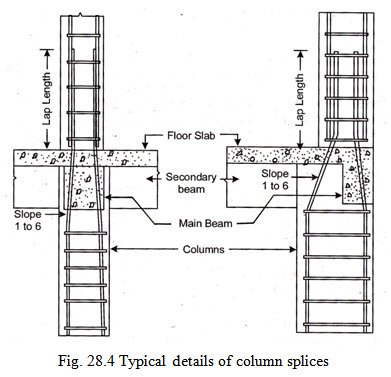
(vi) Where it is necessary to splice the longitudinal reinforcement, the bars shall over-lap for a distance of not less than 24 times the diameter of the smallest bar.
(vii) If on account of architectural considerations or otherwise a column has a large cross-sectional area than that required to support the load, the minimum percentage of steel shall be based upon the area of concrete required to resist the direct stress (i.e., the cross-sectional area of column required as per design) and not upon the actual area.
(viii) In the case of pedestals in which the steel reinforcement is not taken in to account in strength calculations, nominal longitudinal reinforcement not less than 0.15% of the cross-sectional area shall be provided.
Note. Pedestal is a compression member, the effective length of which does not exceed three the least lateral dimension.
Transverse reinforcement: To safeguard the longitudinal reinforcement against buckling, the transverse reinforcement may be provided either in the form of ties or helical reinforcement (spiral).
(i) The minimum diameter of the lateral ties or helical reinforcement (spiral) shall not be less than ¼th of the diameter of the largest longitudinal bars and in no case less than 5 mm.
(ii) The maximum diameter of the ties should preferably be not more than 12 mm.
(iii) The pitch of the ties should not be more than the least of the following distances.
(a) The least lateral dimension of the column.
(b) 16 times the smallest diameter of the longitudinal reinforcement bar to be tied.
(c) 48 times the diameter of lateral tie or transverse reinforcement.
In cases where the column is assumed to take increased load on account of the continuous helical binding or spiral reinforcement, the following requirement in respect of the pitch of the helical reinforcement should be strictly followed.
(iv) The pitch of the helical turns should not be more than the least of the following distances:
(a) \[\frac{1}{6}th\] of the core diameter upto centre of helix.
(b) 75 mm.
(v) The least spacing of the lateral ties may be 150mm and for the spirals the minimum pitch shall be 25 mm or 3 times the diameter of the helical reinforcement member whichever is greater.
Fig. 28.3 and Fig. 28.4 shows the typical details of column splices.
28.8 ARRANGEMENT OF TRANSVERSE REINFORCEMENT
As per IS : 456-1978, the arrangement of transverse reinforcement in a compression member shall be as under:
-
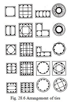
If the longitudinal bars are not spaced more than 75 mm on either side, transverse reinforcement need only to go round corner and alternate bars for the purpose of providing effective lateral supports as shown in Fig. 28.5 (a).
-
If the longitudinal bars spaced at a distance of not exceeding 48 times the diameter of the tie effectively tied in two directions, additional longitudinal bars in between these bars need to be tied in one direction by open ties as shown in Fig. 28.5 (b).
-
When the longitudinal reinforcing bars in a compression member are placed in more than one row, effective lateral support to the longitudinal bars in the inner rows may be assumed to have been provided if:
(i) Transverse reinforcement is provided for the outer-most row.
(ii) No bar of the inner row is close to the nearest compression face than three times the diameter of the largest bar in the inner row as shown in Fig. 28.5 (c) and (d).
28.9 STEPS TO BE FOLLOWED IN THE DESIGN
Fig. 28.6 shows the arrangement of ties for different numbers of column bars. The various steps involved in the design of a column, with independent or separate links, are given below:
(a) Find the load the column is required to carry. Add the self-weight of column to get the total load at the column base.
(b) Decide the grade of concrete and hence the stress in concrete to be adopted in the design.
(c) Depending upon the load, assume, suitable area of reinforcement \[({A_{sc}})\] = 1 to 2% of gross area (A) of column. Determine approximate area (A) of the column by the formula
\[P = {\sigma _{cc}}\left( {A - {A_{sc}}} \right) + {\sigma _{sc}}{A_{sc}}\]
If \[{A_{sc}}\] assumed = 1%A = 0.01A
Then
(d) Having found the value of A from the above equation, find out the least dimension (b) of the column. In case, it is desired to have a square column, b= \[\sqrt A\] . While if a circular column of \[\phi\] (b) is desired
\[b = \sqrt {\frac{{4A}}{\pi }}\]
(e) Find the effective length \[({l_{ef}})\] , of the column from the given end conditions. If \[\frac{{{l_{ef}}}}{b} < 12\] it becomes a case of short column. In such a case drop the steps (f) and (g) given below and then proceed.
(f) If \[\frac{l}{b} > 12\] \[= 12\] or it becomes a case of long column. In such a case find the reduction co-efficient \[{C_r}\] given by \[{C_r} = 1.25 - \frac{{{l_{ef}}}}{{48b}}\]
(g) Calculate the load P’ for which an equivalent short column should be designed.
\[P' = \frac{P}{{{C_r}}}\]
Now substitute this value of load, in step (c) and calculate the final area of column and hence determine the final size of column.
(h) Calculate area of longitudinal reinforcement and choose suitable diameter of longitudinal reinforcement.
(i) Find the diameter of the bar to be used as ties, and find pitch of ties in accordance with rules.
Example 28.1
(a) A reinforced concrete column is 400 mm x 400 mm in size and has an effective length of 4500 mm. The column is reinforced with 8 Nos of 20 mm \[\phi\] bars and the grade of concrete used in the work is M 15. Find the magnitude of safe load that such a column can carry.
(b) What will be the magnitude of safe load if the effective length of the column is increased to 8000 mm.
Solution (a) In this case \[{l_{ef}} = 4500mm\]
\[b = 400mm\]
The ratio \[\frac{{{l_{ef}}}}{b} = \frac{{4500}}{{400}} = 11.25\]
Since it is less than 12, the column is to be treated as a short column.
Load carrying capacity of a short column is given by \[{\text{P}} = {\text{}}{\sigma _{cc}}.{A_c} + {\sigma _{sc}}.{A_{sc}}\]
From M 15 grade of concrete \[({\sigma _{cc}})\] = \[4\frac{N}{{m{m^2}}},{\sigma _{sc}} = 130N/m{m^2}\]
\[{A_{sc}} = 8.\frac{\pi }{4}{\left( {20} \right)^2} = 2513m{m^2}\]
\[A = 400 \times 400 = 160000m{m^2}\]
\[{A_c} = A - {A_{sc}} = 160000 - 2513 = 157487m{m^2}\]
Substituting the values in formula above, we get
\[P = \left( {4 \times 157487 + 130 \times 2513} \right) = 956638N = 956.6kN\]
(b) In this case \[{l_{ef}} = 8000mm\]
The ratio \[\frac{{{l_{ef}}}}{b} = \frac{{8000}}{{400}} = 20\]
which is greater than 12. Hence the column is to be treated as a long column.
Reduction factor, \[{C_r} = 1.25 - \frac{{{l_{ef}}}}{{48b}} = 1.25 - \frac{{8000}}{{48 \times 400}} = 0.833\]
Load carrying capacity of the long column
\[= Loadcarryigcapacityoftheshortcolumnx{C_r}\]
\[= 956638 \times 0.833 = 797198N = 797.2kN\]
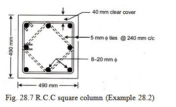
Example 28.2 Design a short R.C. column required to carry an axial load of 1500 kN. Use M 20 grade of concrete and mild steel reinforcement.
Solution The permissible stress for concrete in direct compression \[({\sigma _{cc}})\] for M 20 grade of concrete \[= 5N/m{m^2}\]
Let the area of longitudinal reinforcement \[({A_{sc}})\]
= 1% of cross-sectional area (A) of the column = 0.01A mm2
The load carrying capacity of a short column is given by
\[P = {\sigma _{CC}}.{A_c} + {\sigma _{sc}}.{A_{sc}} = {\sigma _{CC}}\left( {A - 0.01A} \right) + {\sigma _{sc}} \times 0.01A\]
\[1500 \times {10^3} = 5\left( {A - 0.01A} \right) + 130 \times 0.01A = 4.95A + 1.3A = 6.25A\]
or \[A = \frac{{1500x{{10}^3}}}{{6.25}} = 240000m{m^2}\]
One side (b) of a square column = \[\sqrt A\]
\[b = \sqrt {240000}= 489mmsay490mm\]
Hence provide a square column of size 490 mm x 490 mm
Area of longitudinal reinforcement \[= 0.01 \times 240000 = 2400m{m^2}\]
Using 20 mm \[\phi\] bars \[\left( {{A_\phi } = \frac{\pi }{4} \times {{\left( {20} \right)}^2} = 314m{m^2}} \right)\]
No. of bars required = \[\frac{{2400}}{{314}} = 7.64say8Nos\]
Design of ties : The diameter of the ties should not be less than 1/4 the diameter of the largest longitudinal bar subject to a minimum of 5 mm.
Hence adopt dia. of ties = 5mm
The c/c spacing of the ties should be least of the following:
(i) least lateral dimension of column = 490mm
(ii) 16 x \[\phi\] of longitudinal bar = 16 x 20 = 320mm
(iii) 48 x \[\phi\] of tie = 48 x 5 = 240mm
Hence provide 5mm \[\phi\] @ 240 mm c/c as shown in the Fig. 28.7.
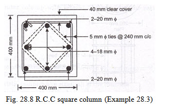
Example 28.3 A 400 mm x 400 mm column 12000 mm long is restrained at both ends and is required to carry an axial load of 900 kN. Design the column using M 20 grade of concrete and mild steel reinforcement.
Solution: For M 20 grade of concrete
\[({\sigma _{cc}})\] = \[5\frac{N}{{m{m^2}}},{\sigma _{sc}} = 130N/m{m^2}\]
Effective length of the column \[{l_{ef}} = 0.65 \times 12000 = 7800mm\]
The ratio ![]()
Hence the column is a long column.
Reduction factor, \[{C_r} = 1.25 - \frac{{{l_{ef}}}}{{48b}} = 1.25 - \frac{{7800}}{{48 \times 400}} = 0.844\]
Design load for a short column \[= \frac{P}{{{C_r}}} = \frac{{900}}{{0.844}} = 1066kN\]
Hence the column can now be designed as a short column for a design load of 1066 kN.
\[P = {\sigma _{CC}}.\left( {A - {A_{sc}}} \right) + {\sigma _{sc}}.{A_{sc}}\]
\[1066 \times {10^3} = 5\left( {400 \times 400 - {A_{sc}}} \right) + 130 \times {A_{sc}}\]
\[{A_{sc}} = 2128m{m^2}\]
Provide a combination of 20 mm \[\phi\] and 18 mm \[\phi\] bars so as to have 8 bars giving
\[{A_{sc}} = 2128m{m^2}approx\]
Area of 20 mm \[\phi\] bar \[\left( {{A_\phi } = \frac{\pi }{4} \times {{\left( {20} \right)}^2} = 314m{m^2}} \right)\]
Area of 18 mm \[\phi\] bar \[\left( {{A_\phi } = \frac{\pi }{4} \times {{\left( {18} \right)}^2} = 254m{m^2}} \right)\]
Area provided by 4 - 20 mm \[\phi\] + 4 - 18 mm \[\phi\] bars \[= 4 \times 314 + 4 \times 254 = 2272m{m^2}\]
Hence provided by 4 - 20 mm \[\phi\] + 4 - 18 mm \[\phi\] bars
Design of ties : The diameter of the ties should not be less than 1/4 the diameter of the largest longitudinal bar or 5 mm whichever is more.
Hence adopt dia. of ties = 5mm
The c/c spacing of the ties should be least of the following:
(i) Least lateral dimension of column = 400 mm
(ii) 16 x \[\phi\] of longitudinal bar \[= 16 \times 18 = 288mm\]
(iii) 48 x \[\phi\] of tie \[= 48 \times 5 = 240mm\]
Hence provide 5 mm \[\phi\] ties @ 240 mm c/c as shown in the Fig. 28.8.
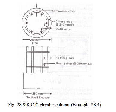
Example 28.4 Design a short circular R.C. column to carry an axial load of 388 kN. The column is to be provided with circular lateral ties. Adopt M 20 grade of concrete and mild steel reinforcement.
Solution The load carrying capacity of a short column is given by
\[P = {\sigma _{CC}}.{A_c} + {\sigma _{sc}}.{A_{sc}}\]
Let the area of longitudinal reinforcement \[({A_{sc}})\]
= 2% of cross-sectional area (A) of the column = 0.02A mm2
\[{A_c} = A - {A_{sc}} = A - 0.02A\]
\[P = {\sigma _{CC}}.\left( {A - {A_{sc}}} \right) + {\sigma _{sc}}.{A_{sc}} = {\sigma _{CC}}.\left( {A - 0.02A} \right) + {\sigma _{sc}}.0.02A\]
\[388 \times {10^3} = 5\left( {A - 0.02A} \right) + 130 \times 0.02A = 4.9A + 2.6A = 7.5A\]
or \[A = \frac{{388 \times {{10}^3}}}{{7.5}} = 51733m{m^2}\]
Let D be the diameter of the column
\[A = \frac{\pi }{4}{D^2} = 51733\] or D=257 mm say 260 mm
Hence adopt diameter of the column = 260 mm
Area of longitudinal reinforcement = 0.02 x 51733 = 1035 mm2
Using 16 mm \[\phi\] bar \[\left( {{A_\phi } = \frac{\pi }{4} \times {{\left( {16} \right)}^2} = 201m{m^2}} \right)\]
No. of bars required \[= \frac{{1035}}{{201}} = 5.2say6Nos.\]
Hence provide 6 nos. of 16 mm \[\phi\] bars.
Design of ties : The diameter of the ties should not be less than ¼ the diameter of the largest longitudinal bar subject to a minimum of 5 mm.
In this case ¼ x 16 = 4 mm, hence provide 5mm \[\phi\] circular ties or rings.
The c/c spacing of the ties should be least of the following:
(i) Least lateral dimension of column = 260 mm
(ii) 16 x \[\phi\] of longitudinal bar = 16 x 16 = 256 mm
(iii) 48 x \[\phi\] of tie = 48 x 5 = 240 mm
Hence provide 5 mm circular ties or ring @ 240 mm c/c as shown in the Fig. 28.9.


Last modified: Thursday, 3 April 2014, 5:44 AM