Site pages
Current course
Participants
General
MODULE 1.
MODULE 2.
MODULE 3.
MODULE 4.
MODULE 5.
MODULE 6.
MODULE 7.
MODULE 8.
MODULE 9.
MODULE 10.
MODULE 11.
MODULE 12.
LESSON 26. Design of Two-way Slabs
26.1 INTRODUCTION
It is seen that one way slab supported on two opposite sides has only one plane of bending and thus the main reinforcements are provided in one direction (i.e., parallel to the plane of bending). The load from the slab in such a case is transferred to two supports. In case the slab is supported along all the four sides, it has a tendency to bend into a dished surface when loaded. Thus at any point the slab is curved in two principal directions or develops bending moment in two directions. Such a slab has to be reinforced at the bottom for tension in two direction perpendicular to each other. The load from the slab in such a case is obviously transferred on all the four supporting sides.
This type of behaviour holds good when the ratio between length and breadth of the slab is less than two. For increased ratio of sides, the slab virtually spans along the shorter side and it is designed as one way slab.
Two way slabs can be divided in following three categories:
(1) Slabs, simply supported along four edges with corners free to lift and loaded uniformly.
(2) Slabs, simply supported along four edges with corners held down and loaded uniformly.
Slabs with edges fixed or continuous and loaded uniformly.
26.2 SLABS SIMPLY SUPPORTED ALONG FOUR EDGES WITH CORNERS FREE TO LIFT AND LOADED UNIFORMLY
These slabs are commonly used as isolated roof slabs for individual rooms in single storeyed buildings. Thus the slabs are laid non-continuous on all the four edges and are not restrained by supporting walls or beams. Since the corners of the slab are not held down, no torsional reinforcements are provided in the slab. The design of such a slab can be carried out by following two methods.
(i) Rankine-Grashoff Theory method, and
(ii) I.S. Code method.
26.2.1 Rankie-Grashoff Theory Method
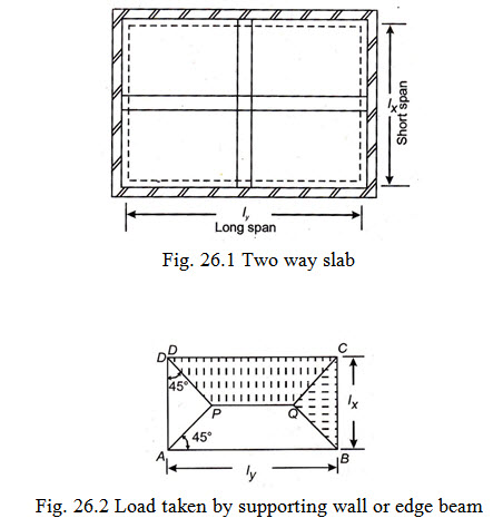
Let \[{l_x}\] and \[{l_y}\] represent the effective lengths of the slab along the shorter and longer spans respectively as shown in Fig. 26.1. Let w kN/m2 be the design load on the slab \[{w_x}\] and \[{w_y}\] be the distribution of w acting on strips parallel to \[{l_x}\] and \[{l_y}\] respectively.
Now according to Rankine – Grashoff Theory, the load (w) is so split up into \[{w_x}\] and \[{w_y}\] that the deflection at the central point O common to both strips must be the same. The statement can be divided into two parts
i.e., \[{w_x} + {w_y} = w\] …(i)
and \[\frac{{5{w_x}l_x^4}}{{384EI}} = \frac{{5{w_y}l_y^4}}{{384EI}}\] …(ii)
Simplifying (ii), we have
\[\frac{{{w_x}}}{{{w_y}}} = {\left( {\frac{{{l_y}}}{{{l_x}}}} \right)^4}\]
Let \[\frac{{{l_y}}}{{{l_x}}} = r\]
\[\frac{{{w_x}}}{{{w_y}}} = {r^4}or{w_x} = {w_y}{r^4}\] …(iii)
Since \[w = {w_x} + {w_y}\] therefore \[{w_x} = w - {w_y}\] …(iv)
Equating (iii) and (iv), we have
\[w - {w_y} = {w_y}{r^4}\] or \[{w_y} = \frac{1}{{1 + {r^4}}}w\] …(v)
Similarly \[{w_x} = \frac{{{r^4}}}{{1 + {r^4}}}w\] …(vi)
Having evaluated \[{w_x}\] and \[{w_y}\] , the bending moments in the slab can be worked out by the following formulae.
B.M. per metre width along short span ( Mx ) = \[{w_x}.\frac{{l_x^2}}{8}\]
B.M. per metre width along short span ( My ) = \[{w_y}.\frac{{l_y^2}}{8}\]
The bending moments in the short span being larger, govern the depth of a two way slab. The reinforcement parallel to short span ( lx ) should be placed below the reinforcement parallel to long span(ly). From this arrangement of reinforcement it is seen that the effective depth of slab for long span will be smaller.
Design of slab by use of table :
Equation Nos. (v) and (vi) can be written as
\[{w_y} = {k_y}.w\] …(vii)
\[{w_x} = {k_x}.w\] …(viii)
where \[{k_y} = \frac{1}{{1 + {r^4}}}and{k_x} = \frac{{{r^4}}}{{1 + {r^4}}}\]
It is obvious that the value of \[{k_y}\] and \[{k_x}\] depend upon r and the ratio of length of slab \[({l_y})\] to the breadth \[({l_x})\] of the slab. The Table 26.1 gives values of \[{k_y}\] and \[{k_x}\] for different values of \[\frac{{{l_y}}}{{{l_x}}}\] or r.
TABLE 26.1
|
\[\frac{{{l_y}}}{{{l_x}}} = r\] |
\[{k_x}\] |
\[{k_y}\] |
\[\frac{{{l_y}}}{{{l_x}}} = r\] |
\[{k_x}\] |
\[{k_x}\] |
|
1.00 |
0.50 |
0.50 |
1.40 |
0.79 |
0.21 |
|
1.05 |
0.55 |
0.45 |
1.50 |
0.84 |
0.16 |
|
1.10 |
0.59 |
0.41 |
1.60 |
0.87 |
0.13 |
|
1.15 |
0.64 |
0.36 |
1.75 |
0.90 |
0.10 |
|
1.20 |
0.68 |
0.32 |
2.00 |
0.94 |
0.06 |
|
1.25 |
0.71 |
0.29 |
2.50 |
0.97 |
0.03 |
|
1.30 |
0.74 |
0.26 |
3.00 |
0.98 |
0.02 |
After knowing the value of \[{k_x}\] and \[{k_y}\] for the given ratio of \[\frac{{{l_y}}}{{{l_x}}}\] or r , the bending moments in the slab can be worked out by the following formulae.
B.M. per metre width along short span (Mx) \[ = {w_x}.\frac{{l_x^2}}{8} = {k_x}.\frac{{wl_x^2}}{8}\] …(ix)
And B.M. per metre width along long span (My) \[ = {w_y}.\frac{{l_y^2}}{8} = {k_y}.\frac{{wl_y^2}}{8}\] …(x)
A review of table indicates that for the ratio of \[\frac{{{l_y}}}{{{l_x}}} = 2,\] the share of total load carried by long span is only 6% and hence it is assumed that such a slab acts almost as a slab spanning in one direction i.e., along the shorter span.
26.2.2 IS Code Method
IS 456-1978 has given a simple method for designing simply supported slabs which do not have adequate provision to resist torsion at corners and to prevent the corners from lifting. In this method the maximum bending moments per unit width of slab are given by the following formulae.
B.M. per unit width along short span \[{M_x} = { \propto _x}.wl_x^2\]
B.M. per unit width along long span \[{M_y} = { \propto _y}.wl_x^2\]
where \[w = totaldesignloadperunitarea\]
\[{l_x} = lengthoftheshorterspan\]
\[{ \propto _x}and{ \propto _y}aretheco - efficientsgiveninTable26.2.\]
TABLE 26.2 Bending moment co-efficients for slabs spanning in two direction at right angles, simply supported on four sides.
|
\[\frac{{{l_y}}}{{{l_x}}} = \] |
1.0 |
1.1. |
1.2 |
1.3 |
1.4 |
1.5 |
1.75 |
2.0 |
|
\[{ \propto _x}\] |
0.062 |
0.074 |
0.084 |
0.093 |
0.099 |
0.104 |
0.113 |
0.118 |
|
\[{ \propto _y}\] |
0.062 |
0.061 |
0.059 |
0.055 |
0.051 |
0.046 |
0.037 |
0.029 |
Irrespective of the type of method adopted in design, at least 50% of the tension reinforcement provided at mid-span should be extended to the supports. The remaining 50% should extend to within 0.1\[{l_x}\] or 0.1\[{l_y}\] of the support respectively.
26.3 SHEAR FORCE ON THE EDGES OF A TWO-WAY SLAB
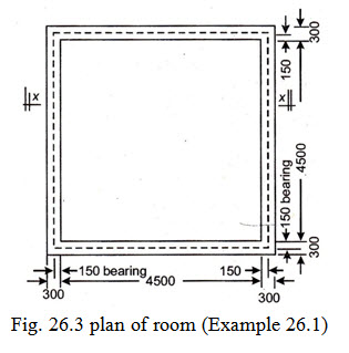
The total load of two-way slab loaded with uniformly distributed load and supported on all the four edges is assumed to be transmitted to the supporting walls or edge beams in the manner as shown in Fig. 26.2. The slab is assumed to be divided into two triangles and two trapeziums by lines, AP, DP, BQ and CQ drawn at 45˚ through the corners ABCD. The load due to the triangular portions of the slab is assumed to be carried by the edge beams or supporting walls, parallel to the width of the slab and that due to the trapezoidal portions of slab is assumed to be carried by the edge beams or walls parallel to length of the slab.
This form of distribution of load holds good both for simply-supported slabs as well as restrained two way slabs.
To find maximum shear force per unit width along short span: From the above it is seen that the total load on edge BC \[ = w \times Areaof\Delta BQC = w \times \frac{{l_x^2}}{4}\]
Average reaction per unit width along BC \[ = \frac{{wl_x^2}}{4} \times \frac{l}{{{l_x}}} = \frac{{w{l_x}}}{4}\]
However the maximum reaction per unit width along BC will occur near centre of BC and its value may be taken as \[\frac{{w{l_x}}}{3}\] . Similarly the shear force per unit width along the long edge AB or CD may be taken as \[w{l_x}.\frac{r}{{2 + r}}\]
26.4 STEPS TO BE FOLLOWED IN THE DESIGN
The design procedure of two way slabs, simply supported along four edges with corners free to lift and loaded uniformly can be divided into the following steps:
(a) Calculate the effective spans both in respect of short span ( \[{l_x}\] ) as well as long span ( \[{l_y}\] ).
(b) Calculate (w) i.e., total design load; w=sum of total dead loaded including self wt. of slab, wt. of finishing (flooring, terracing, ceiling plaster etc.) and other fixed type of imposed loads (if any) + total live load and any other not fixed type of imposed load.
(c) Calculate bending moments per unit width along short span and long spans by the governing formulae depending upon the method of design and adopted.
(i) Based on Rankine-Grashoff Theory method
\[{M_x} = {w_x}.\frac{{l_x^2}}{8}\]
\[{M_y} = {w_y}.\frac{{l_y^2}}{8}\]
\[{w_x} = loadperunitrunalongshortspan\]
\[{w_y} = loadperunitrunalongshortspan\]
(ii) Based on I.S. Code method
\[{M_x} = { \propto _x}.wl_x^2\]
\[{M_y} = { \propto _y}.wl_x^2\]
\[{ \propto _x}\] , \[{ \propto _y}\] being obtained from Table 26.2.
(d) Calculate the effective depth of the slab by taking bigger of the two values of the bending moments by the formula \[d = \sqrt {\frac{{{M_{max}}}}{{R.b}}}\]
(e) Calculate the area of steel per metre width along each span by the formulae :
Area of steel per metre width along short span \[ = \frac{{{M_x}}}{{j.d.{\sigma _{st}}}}\] sq. mm
Select suitable diameter ( \[{\phi _x}\] ) of the bar and find their centre to centre spacing.
Area of steel per metre width along long span \[ = \frac{{{M_x}}}{{j.\left( {d - {\phi _x}} \right).{\sigma _{st}}}}sq.mm\]
Select suitable diameter of bar and find their centre to centre spacing.
(f) Calculate distribution steel at the rate of 0.15% of the gross sectional area of the concrete if plain m.s. bars are used as reinforcement. In case high-yield strength deformed bars (HYSD) are used as reinforcement this % may be taken as 0.12%.
(g) Check for shear
(i) Calculate shear force per unit width along short edge by the formula \[V = \frac{{w{l_x}}}{3}\]
(ii) Calculate shear force per unit width along long edge by the formula \[V = w{l_x}\frac{r}{{2 + r}}\]
where r = \[\frac{{{l_y}}}{{{l_x}}}\]
(iii) Calculate shear force per unit width along long edge by the formula \[{\tau _v} = \frac{V}{{b.d}}\]
Further steps relating to check for shear are same as applicable to the design of one-way slab.
(h) Check for development length at supports by the formula ![]()
Example 26.1 Design an R.C.C. floor slab for a residential building over a single room 4.5 m x 4.5 m clear inside dimensions with 1½ brick walls for support on all the sides. Use M 15 grade of concrete and mild steel reinforcement. Make usual assumptions based on I.S. codes.
Solution: Following assumptions have been made in the design.
(i) That the floor slab is finished with 25 mm thick flooring and the slab is provided with ceiling plaster to present a smooth ceiling finish.
(ii) The live load on the floor is 2000 \[N/{m^2}\] .
(iii) The slab is simply supported on all the four sides with corners not held down.
(iv) The bearing of the slab on supporting walls is 150 mm.
Fig. 26.3 shows the dimension of room.
Design constants
For M 15 grade of concrete and mild steel reinforcement
\[{\sigma _{cbc}} = 5N/m{m^2}\]
\[{\sigma _{st}} = 140\frac{N}{{m{m^2}}}andm = 19\]
\[k = 0.404;j = 0.865andR = 0.874\]
Let the overall depth of slab = 150 mm
Assuming 10 mm \[\phi\] main bar and clear cover = 15 mm
Effective depth of slab (d) = \[150 - \frac{{10}}{2} - 15 = 130mm\]
Effective span shall be smaller of the following
(a) c/c of bearing i.e. 4500 + 150 = 4650 mm or
(b) Clear span + (d) = 4500 + 130= 4630 mm
\[{l_x} = {l_y} = 4630mm\]
Load per square metre
(i) Due to self wt. of slab = 0.150 x 25000 = 3750
(ii) Floor finish = 0.025 x 24000 = 600
(iii) Ceiling plaster (Lump sum) = 160
(iv) Live load = 2000
------------------
Total = 6510 = 6.51
\[\frac{{{l_x}}}{{{l_y}}} = \frac{{4.630}}{{4.630}} = 1\]
Portion of the load carried by short span = Portion of load carried by long span
\[= \frac{{6.51}}{2} = 3.255kN/{m^2}\]
Consider a strip of slab one metre wide
Load per metre (w) \[= 3.225kN/m\]
Max. bending moment (M) along each span \[ = \frac{{w{l^2}}}{8} = \frac{{3.225x{{4.63}^2}}}{8} = 8.72kNm\]
\[= 8.72 \times {10^6}Nmm\]
\[d = \sqrt {\frac{M}{{R \times 1000}}}= \sqrt {\frac{{8.72 \times {{10}^6}}}{{0.874 \times 1000}}}= 99.9mm\]
Required effective depth from stiffness/deflection consideration
\[ = \frac{{Span}}{{3.5}} = \frac{{4.63 \times 1000}}{{35}} = 132mm\]
Provide overall depth of slab = 150 mm
and effective depth = 130 mm
Area of reinforcement along one span (say \[{l_x}\]).
\[{A_{s{t_x}}} = \frac{M}{{j.d.{\sigma _{st}}}} = \frac{{8.72x{{10}^6}}}{{0.865 \times 130 \times 140}} = 554m{m^2}\]
c/c spacing of 10 mm \[\phi\] bars \[({A_\phi } = 78.5m{m^2}) = \frac{{78.5 \times 1000}}{{554}} = 141.7mmsay140mmc/c\]
Hence provide 10mm \[\phi\] bars @ 140 mm c/c along one span.
Bend up alternate bar at \[\frac{{4630}}{7} = 661.4mm\]
Say 660 mm from the centre of bearing.
Area of reinforcement along the span (or \[{l_y}\] ) perpendicular to the above span.
\[{A_{st}}_y = \frac{M}{{j \times \left( {130 - 10} \right) \times 140}} = \frac{{8.72 \times {{10}^6}}}{{0.865 \times 120 \times 140}} = 600m{m^2}\]
c/c spacing of 10 mm \[\phi\] bars \[= \frac{{78.5 \times 1000}}{{600}} = 131mmsay130mmc/c\]
Actual \[{A_{st}}\] provided \[= \frac{{1000 \times 78.5}}{{130}} = 604m{m^2}\]
Bend up alternate bars at \[l/7\] \[= 660mmfromthecentreofbearing\]
Distribution reinforcement \[{A_{sd}} = \frac{{0.15 \times b \times D}}{{100}} = \frac{{0.15 \times 1000 \times 150}}{{100}} = 255m{m^2}\]
c/c spacing of 6mm \[\phi\] bars \[({A_\phi } = 28.3m{m^2})\]
\[= \frac{{1000 \times 28.3}}{{225}} = 125mmc/csay120c/c\]
check for shear:
Max. shear force per metre length on any one of the sides
\[V = \frac{{w.{l_x}}}{3} = \frac{{6.51x4.63}}{3} = 10.05kN\]
\[{\tau _v} = \frac{V}{{bd}} = \frac{{10.05 \times 1000}}{{1000 \times 130}} = 0.078N/m{m^2}\]
Permissible shear stress \[{\tau _c}\] from Table 22.1 will work out to be much more than 0.078 N/mm2, hence safe.
Check for development length: As per code \[\frac{{{M_1}}}{V} + {L_o} > {L_d}\]
Since alternate bars are bent up near support, area of tensile reinforcement available at support
\[= \frac{1}{2}x604 = 302m{m^2}\]
Now \[{M_1} = {\sigma _{st}}.{A_{st}}.j.d = 140 \times 302 \times 0.865 \times 130 = 4.75 \times {10^6}Nmm\]
\[V = 10.05kN = 10.05 \times 1000N\]
\[{L_o} = \left( {\frac{{{l_s}}}{2} - c' - \phi } \right) + 16\phi= \frac{{{l_s}}}{2} - c' + 13\phi= \frac{{150}}{2} - 25 + 13 \times 10\]
\[= 180mm\]
\[\frac{{{M_1}}}{V} + {L_o} = \frac{{4.75 \times {{10}^6}}}{{10.05 \times {{10}^3}}} + 180 = 473 + 180 = 653mm\]
\[{L_d} = \frac{{\phi {\sigma _{st}}}}{{4{\tau _{bd}}}} = \frac{{10 \times 140}}{{4 \times 0.6}} = 583mm\]
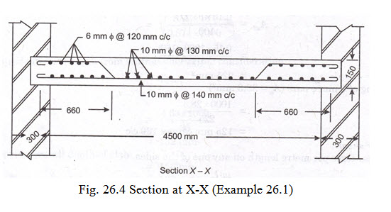
Since \[\frac{{{M_1}}}{V} + {L_o} > {L_d}\] hence safe. Fig. 26.4 shows the section at X-X.
Last modified: Friday, 28 March 2014, 11:31 AM