Site pages
Current course
Participants
General
MODULE 1.
MODULE 2.
MODULE 3.
MODULE 4.
MODULE 5.
MODULE 6.
MODULE 7.
MODULE 8.
MODULE 9.
MODULE 10.
MODULE 11.
MODULE 12.
LESSON 31. Cantilever Retaining Walls
31.1 INTRODUCTION
Retaining walls are structures constructed for the purpose of retaining earth or other materials like coal, ore, water etc. It may also be defined as a wall provided to maintain ground at two different levels. Provisions of retaining walls become necessary in the construction of hill roads, embankments, bridge abutment, basement in buildings, water reservoir, in preventive measures against soil erosion, in landscaping etc. The material retained by the wall is generally known as backfill. The backfill may be horizontal i.e., levelled with the top of wall or it may be inclined at certain angle to the top. The inclined fill is also known as surcharge. Besides loads due to retained material, the retaining wall may also be subjected to surcharged load (due to automobile, rail road etc.) acting directly on the wall as well as on the backfill. The retaining wall should be stable enough to resist all type of forces acting on it.
31.2 TYPES OF RETAINING WALLS
Based on the method of achieving stability, retaining walls are classified into the following types:
(i) Gravity walls
(ii) Cantilever retaining walls
(iii) Counterfort retaining walls
(iv) Buttressed walls.
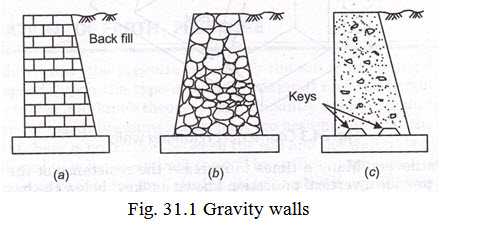
31.2.1 Gravity Walls
These walls are constructed in brick masonry, stone masonry or plain cement concrete and it is shown in Fig. 31.1. The wall is so proportioned that the dead weight of the wall provides required stability against the thrust exerted by the backfill including surcharge (if any). The size of the wall is so kept that there is no tensile stress developed at any section of the wall under any condition of loading.
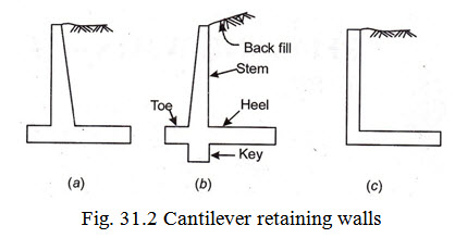
31.2.2 Cantilever Retaining Walls
These are R.C.C. walls made in the form of an invented T as shown in Fig. 31.2. This type of wall proves to be economical for moderate heights say 6 to 7m. The wall consists of three components, (i) the stem, (ii) the toe, and (iii) the heel. Each of these components are designed as a cantilever. The stability of the wall is partially provided by the weight of earth on the heel. Sometimes the cantilever wall is constructed in the form of L. In this case wall has only two components i.e., (i) the stem and (ii) the heel, each being designed as cantilevers. Many a times to increase the resistance of the wall to sliding it becomes necessary to provide a vertical projection known as “key” below the base of the wall. This type of wall with a key is shown in Fig.31.2 (b).
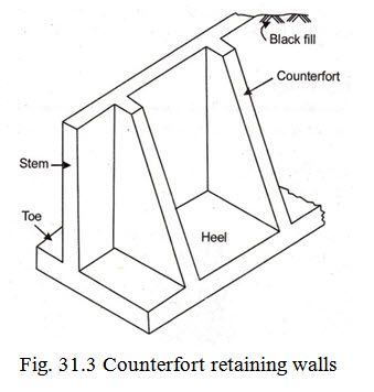
31.2.3. Counterfort Retaining Walls
When the height of the retaining wall to be provided exceeds 6 to 7m, counterfort retaining wall prove to be economical. In this type of wall the base slab as well as the stem of the wall span horizontally as continuous slabs between vertical brackets known as counterforts as shown in Fig. 31.3. The counterforts are provided behind the wall (on the backfill side) and are subjected to tensile forces. The spacing of the counterforts may vary from \[\frac{1}{3}\] to \[\frac{1}{2}\] of the height of wall. The more the height of the wall, the closer should be the spacing of counterforts.
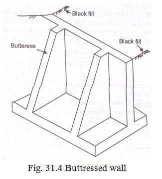
31.2.4 Buttressed Walls
This buttressed wall is identical to a counterfort retaining wall with the main difference that the vertical brackets are provided in front of the wall (on face opposite to the face retaining back fill) as shown in Fig. 31.4. The brackets in this case are known as buttresses and by virtue of their location they are subjected to compressive forces.
31.3 DETERMINATION OF EARTH PRESSURE
It is necessary to determine, the pressure exerted by the soil in designing a retaining wall. The pressure mainly depends upon the type of backfill material and the height of wall. Out of the number of theories evolved, Rankine’s theory is predominantly used in calculating the soil pressure. The Rankine’s theory of earth pressure is based on the assumption that the retained soil is dry, cohesionless and that there is no friction between the soil and the wall. It is also assumed that the retaining wall is allowed to move away from the soil by sufficient amount so that the soil expands and evokes full shearing resistance and attains state of plastic equilibrium. The pressure thus developed is termed as soil earth pressure.
Application of Rankine’s theory for the following cases has been dealt in this lesson.
-
Wall retaining dry and levelled backfill.
-
Wall retaining submerged backfill.
-
Wall retaining partly submerged backfill.
-
Wall with backfill levelled and subjected to uniform surcharge.
-
Wall retaining backfill in slope.
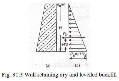
Case 1. Wall retaining dry and levelled backfill : Refer Fig. 31.5 for the case of retaining wall where the backfill to be retained is dry or moist and it is levelled with the top surface of the wall. As per Rankine’s theory, the intensity of active earth pressure per unit vertical area of the wall at any depth h below the top of the wall is given by the relation
\[{p_a} = {\text{\gamma }}.h.\frac{{1 - sin\phi }}{{1 + sin\phi }}\]
where
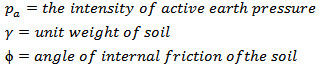
The above relation is further simplified as \[{p_a} = {\text{\gamma }}.h.{k_\alpha }\]
where \[{k_\alpha } = \frac{{1 - sin\phi }}{{1 + sin\phi }}\] and it termed as coefficient of internal friction.
Hence the intensity of active soil pressure at the base of the wall where h = H is given by
\[{p_a} = g.H.{k_\alpha }\]
Rankine’s theory assumes that the distribution of pressure along the height of the wall is triangular and the centre of pressure lies at \[\frac{1}{3}\] rd the height of wall from the base.
∴ Total active soil pressure \[({p_a})\] = Area of the pressure triangle
\[= \frac{1}{2}{\text{\gamma }}.H.{k_\alpha } \times H\]
or \[{p_a} = \frac{1}{2}{\text{\gamma }}{{\text{H}}^2}{k_\alpha }\] acting at H/3 from the base.
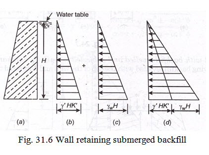
Case 2. Wall retaining submerged backfill: If the water table is such that the retained soil remain fully submerged, in such a case the saturated soil results in increasing the weight of the backfill, decreases the angle of repose of the soil which ultimately amounts to increase in pressure on the wall. Refer Fig. 31.6. The lateral pressure exerted by the submerged soil is considered to comprise of the following two components.
(i) Lateral pressure due to submerged soil
(ii) Lateral pressure due to hydrostatic pressure
Due to buoyancy the weight of submerged soil will be less and its repose will also be much less. Hence the intensity of earth pressure at any depth ‘h’ below the tap of the wall is given by
\[{p_a} = {\text{\gamma }}h.k{'_a} + a{\gamma _{w.}}h\]
where,
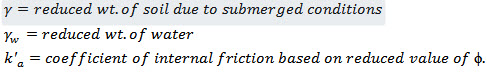
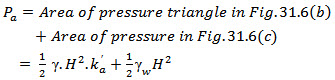
The intensity of pressure at the base of the wall where h = H is given by
\[{p_a} = {\text{\gamma }}H.k{'_a} + {\gamma _{w.}}H\]
Hence total lateral earth pressure at the base of wall is given by
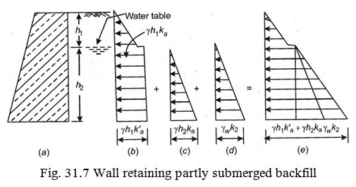
Case 3. Wall retaining partly submerged backfill: In case the water table does not rise up to full height of retaining wall, this will result in a situation where the soil is partially submerged and partly dry.
Refer Fig. 31.7. Let the backfill be moist or dry up to a depth h1 below the top of wall and let the backfill below this depth i.e., be fully submerged. The intensity of lateral pressure at the base of the wall in such a case is given by
\[{p_a} = {\text{\gamma }}{h_1}k{'_a} + {{\text{\gamma }}^1}.{h_2}.k_a^' + {{\text{\gamma }}_w}.{h_2}\]
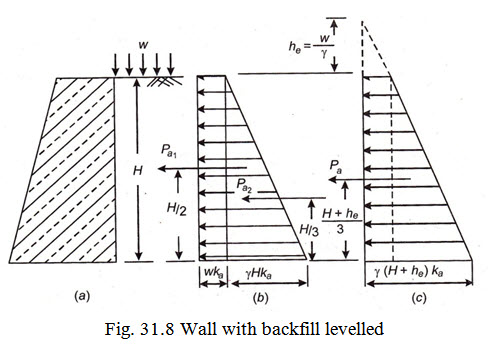
Case 4. Wall with backfill levelled and subjected to uniform surcharge: Fig. 31.8 shows a retaining wall having backfill leveled with the top of the wall and subjected to uniformly distributed surcharged load. Let the intensity of surcharge load per unit area be w. The lateral pressure imposed by this load does not vary with the height and is uniform.
Its value being = \[w.{k_a}\]
Hence total intensity of internal pressure at any depth ‘h’ is \[{p_a} = {\text{\gamma }}.h.{k_a} + w{k_a}\]
The pressure intensity at the base of the wall here h = H is given by
\[{p_a} = {\text{\gamma }}.H.{k_a} + w{k_a}\]
Alternatively, the uniform surcharge load can also converted into equivalent additional fictitious height \[({h_e})\] of the back fill. The height \[({h_e})\] can be obtained by the relationship
\[w.{k_a} = {\text{\gamma }}.{h_e}.{k_a}\]
or \[{h_e} = \frac{w}{{\text{\gamma }}}\]
Hence intensity of pressure at the base of the wall considering the height of backfill = (H + he ) will be
\[{p_a} = {\text{\gamma }}\left( {{H_2} + {h_e}} \right).{k_a}\]
This is shown in pressure diagram in Fig. 31.8 (c).
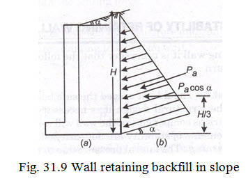
Case 5. Wall retaining back-fill in slope : Fig. 31.9 shows a retaining wall having backfill in slope. Let the slope of surcharged backfill to the horizontal be \[{\text{\alpha }}\] . The angle is also known as angle of surcharge. As per Rankine’s theory, the intensity of pressure at any depth h in case of a wall retaining soil surcharged at an angle \[{\text{\alpha }}\] is given by
\[{p_a} = {\text{\gamma }}h.cos{\text{\alpha }} \times {\text{}}\frac{{cos{\text{\alpha }} - {\text{}}\sqrt {co{s^2}{\text{\alpha }} - co{s^2}\phi } }}{{cos{\text{\alpha }} + {\text{}}\sqrt {co{s^2}{\text{\alpha }} - co{s^2}\phi } }}\]
Its value at the base of the wall here h=H is given by \[{p_a} = {\text{\gamma H}}.cos{\text{\alpha }} \times {\text{}}\frac{{cos{\text{\alpha }} - {\text{}}\sqrt {co{s^2}{\text{\alpha }} - co{s^2}\phi } }}{{cos{\text{\alpha }} + {\text{}}\sqrt {co{s^2}{\text{\alpha }} - co{s^2}\phi } }}\]
It is also assumed that pressure distribution is triangular, the pressure acts parallel to the inclined surface of the backfill and the centre of resultant pressure lies at \[\frac{1}{3}\] rd the height or \[H/3\] above the base.
Hence total pressure \[{P_A} = Areaofthepressuretriangle\]
\[= \frac{1}{2} \times {\text{\gamma }}{H^2}cos{\text{\alpha }}.{\text{}}\frac{{cos{\text{\alpha }} - {\text{}}\sqrt {co{s^2}{\text{\alpha }} - co{s^2}\phi } }}{{cos{\text{\alpha }} + {\text{}}\sqrt {co{s^2}{\text{\alpha }} - co{s^2}\phi } }}\]
31.4. PASSIVE EARTH PRESSURE
If the retaining wall is allowed to move towards the back fill, it will compress the soil and the pressure thus exerted is known as passive pressure.
The intensity of passive earth pressure at any depth ‘h’ in a retaining wall is given by
\[{P_p} = {\text{\gamma }}h.\frac{{1 + {\text{sin}}\phi }}{{1 - {\text{sin}}\phi }} = {\text{\gamma }}.h.{k_p}\]
Where
\[{k_p} = coefficientofpassiveearthpressure,itsvaluebeing = \frac{{1 + {\text{sin}}\phi }}{{1 - {\text{sin}}\phi }}\]
The pressure distribution is triangular.
Hence total passive pressure \[{P_p} = {\text{Areaofpressuretriangular}} = \frac{1}{2} \times {\text{\gamma }}{h^2} \times {k_p}\] acting at \[h/3\] from the base.
31.5 CONDITIONS FOR STABILITY OF RETAINING WALL
To avoid failure of the retaining wall it is necessary that the following requirements are satisfied.
(a) It should not over turn
(b) It should not slide
(c) The max. pressure at toe should not exceed the safe bearing capacity of soil.
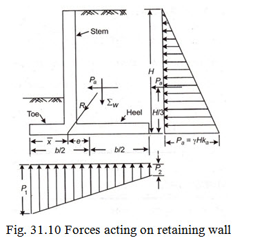
Before proceeding with the structural design it is necessary to ensure that the preliminary dimensions assumed for the various components of the wall will render it safe against above referred types of failures. If the requirements of stability are not satisfied, its dimension should be revised. Refer Fig. 31.10.
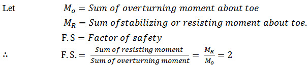
(a)Check against overturning: The lateral pressure due to the backfill and surcharge (if any) tends to overturn the retaining wall about its toe. The overturning moment is stabilized by the weight of wall and the weight of the soil above the heel slab (the weight of soil over the toe is neglected). The retaining wall is considered safe against overturning when the total stabilizing or resisting moment is at least 100% greater than the overturning moment.
(b) Check against sliding. The horizontal component of all lateral pressures tends to slide the wall along its base. The sliding tendency is resisted by the frictional resistance between the base of the wall and the soil underneath. It is a common practice to neglect the passive resistance of the soil in front of the toe of the wall in this check. To meet the requirements of stability, the force of resistance should be 50% more than the sliding force.
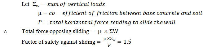
If the factor of safety against sliding works out to be less than 1.5, a key may be provided under the base slab. The passive pressure developed by the key resists sliding and raises the factor of safety to required limit.
(c)Check against maximum pressure at toe:
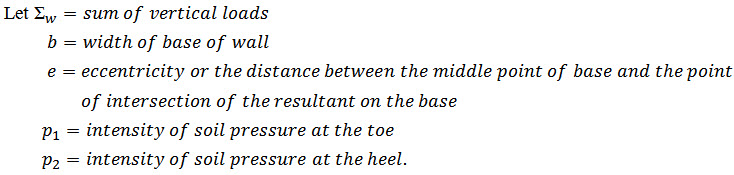
The maximum and minimum pressure are given by
\[{p_1} = \frac{{{\text{\Sigma W}}}}{b}\left( {1 + \frac{{6e}}{b}} \right)\]
\[{p_2} = \frac{{{\text{\Sigma W}}}}{b}\left( {1 - \frac{{6e}}{b}} \right)\]
To meet the requirements of stability \[{p_1}\] should not exceed the safe bearing capacity of soil. In addition, it should be ensured that no tension is developed at the base i.e., the value of \[{p_2}\] should not be negative. To meet this requirement the resultant of the sum of all vertical forces and the horizontal active pressure should cut the base of the wall within the middle third.
31.6 DEPTH OF FOUNDATION
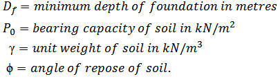
The foundations of the retaining wall should be placed at such a depth where soil of required bearing capacity is available. However, the minimum depth of foundation should not be less then that given by Rankine’s formula according to which
\[{D_f} = \frac{{{P_o}}}{{\text{\gamma }}}{\left( {\frac{{1 - sin\phi }}{{1 + sin\phi }}} \right)^2}\]
Where
31.7 PRELIMINARY DIMENSIONS OF CANTILEVER RETAINING WALL
Prior to start of structural design of a retaining wall it is necessary to adopt some tentative dimensions for different components of the wall. Based on these dimensions the wall is checked for stability (checked for overturning, sliding and maximum pressure at toe) and in case the stability requirements are satisfied, structural design of different wall components is taken up.
Commonly adopted proportions for wall components are as under:
(i) The stem. Depending upon the height (H) of the wall the top width of stem can vary between 200 mm to 300 mm.The bottom width may vary between H/15 to H/10 or it can be decided based on bending moment consideration.
(ii) Base width(b). The base width (b) of the retaining wall vary between 0.4 H to 0.65 H.
For surcharged walls (b) may vary between 0.55 H to 0.75 H.
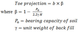
(iii) Toe projection. This may be around b/3. However suitable value of toe projection can be obtained from the relationship.
(iv)Thickness of base slab:
\[\frac{H}{{15}}to\frac{H}{{10}}\]
Last modified: Thursday, 3 April 2014, 11:18 AM