Site pages
Current course
Participants
General
MODULE 1.
MODULE 2.
MODULE 3.
MODULE 4.
MODULE 5.
MODULE 6.
MODULE 7.
MODULE 8.
MODULE 9.
MODULE 10.
MODULE 11.
MODULE 12.
LESSON 29. Design of RCC footing for Wall
29.1 INTRODUCTION
Foundation is that part of a structure which transfers the load of the structure to soil on which it rests. This term includes the portion of the structure below ground level (also known as sub-structure) which provides a base for the structure above the ground (also known as super-structure) as well as the extra provisions made to transmit the loads on the structure including its self wt. to the soil below.
It is often misunderstood that the foundation is provided to support the load of the structure. In fact, it is a media to transmit the load of the structure to the sub-soil. The objectives of foundation are:
(i) To distribute the weight of the structure over larger area so as to avoid over-loading of the soil beneath.
(ii) To load the sub – structure evenly and thus prevent unequal settlement.
(iii) To provide a level surface for building operations.
(iv) To take the sub-structure deep into the ground and thus increase its stability preventing overturning.
29.2 TYPES OF FOUNDATIONS
Foundations can be broadly classified into two types:
(i) Deep foundations, and
(ii) Shallow foundations.
(i) Deep foundations: When the foundations are placed considerably below the lowest part of the super-structure it is termed as deep foundations. Pile foundations, pier foundation, well foundation, cassions etc. fall in the category of deep foundation.
(ii) Shallow foundations: When the foundation is placed immediately beneath the lowest part of the super-structure it is termed as shallow foundation. Shallow foundations can be broadly divided in the following groups:
(1) Spread footings
(2) Combined footings
(3) Mat or raft foundation.
29.2.1 Spread Footings
As the name suggest, in case of spread footings the base of the member (a column or a wall) transmitting the load is made wider so as to distribute the load over a larger area. A footing that supports a single column is known as isolated column footing. In case of a wall, the footing has to be a continuous one and hence it is known as wall footing or a continuous footing. Fig. 29.1 (a) to (e) and Fig. 29.2 (a) and (b) show different types of spread footings.
It is seen that square footing works out to be economical for square and circular columns. Under rectangular column, rectangular footings are considered to be more appropriate. In case the load on column is not large or the size of footing works out to be small requiring small depth of footing it is desirable to keep the thickness of footing uniform. In case the depth of the footing works out to be more, it is common practice to gradually reduce the depth of the footings towards the edges to achieve economy. The footing in such a case is termed as sloped footings.
29.2.2 Combined Footings
A common footing provided for two or more columns in a row is known as combined footing.
29.2.3 Mat or Raft Foundation
It is a large combined footing provided for several columns in two or more rows.
Wall footings (Spread footing) have been described in this lesson.
29.3 DESIGN CRITERIA
The basic requirements for the design of shallow foundations are:
(i) The area of the footing should be such that the maximum pressure on the soil does not exceed the safe bearing capacity of the soil.
(ii) Almost all soils get compressed under load and certain amount of settlement is bound to occur. It is necessary to ensure that the total settlement remain within permissible limits.
(iii) The foundation should be provided in such a manner that the structure does not get tilted under load. If the C.G. of the load does not coincide with the C.G. of the footing, the bearing pressure will not be uniform. In such a case there will be higher pressure on the edge of footing nearer to the C.G. of the load which will cause greater settlement of soil at the edge and this can result in tilting of foundation. This can be avoided by providing the footing area in such a manner that the C.G. of the load coincides with the C.G. of the footing.
(iv) The depth at which the foundation should be located depends on the character of the sub-soil and the magnitude of load on the structure. However the foundation must be carried below:
(a) The depth of frost penetration in region of temperate climate.
(b) The depth at which high volume change in soil due to moisture fluctuation do not cause any adverse effect.
(c) Below the depth of unconsolidated material like muck, garbage dumps, and similar type of made up ground.
(d) The minimum depth prescribed by the local authoricy.
As per IS : 1080- the minimum depth of foundation should not be less than 500 mm. However if good rock is available at smaller depth, only removal of soil may be sufficient for placement of footing.
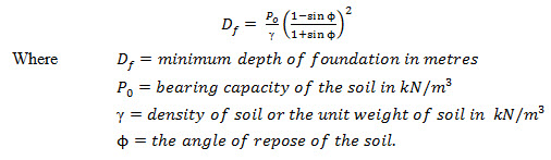
29.4 DEPTH OF FOUNDATION
For all important buildings it is necessary to get the soil investigation of the site carried out by specialist agency. The test report should contain details regarding the type of sub-soil strata at various depths, depth of water table, and recommendation regarding the bearing capacity of soil at different depths. For normal buildings the depth of foundation below ground level is commonly calculated by the Rankine’s formula.
According to Rankine’s formula the minimum depth of foundation is given thus:
29.5 PRESSURE DISTRIBUTION UNDER FOOTINGS
The theory of elasticity analysis as well as the actual observations indicates that the pressure distribution under symmetrically loaded footings is not uniform. The actual stress distribution depends upon the nature of subsoil strata and the rigidity of the footings.
When a rigid footing is placed on loose cohesion-less soil, due to the load transmitted by the footing the soil grains at the edges having no lateral restraint displace laterally and in the centre the soil remain relatively confined. The pressure distribution is such a case is as shown in Fig. 29.3 (a).
On the other hand in case of rigid footing on cohesive soils, the load transmitted by the footing causes very large pressure at the edges and the parabola pressure distribution under the footing in such a case is as shown in Fig. 29.3 (b).
However to simplify the analysis the pressure distribution beneath the footings is assumed to be linear as shown in Fig. 29.3 (c). The design based on this assumption compare fairly well with results of actual studies made in respect of pressure under existing foundations and hence linear pressure distribution is considered to be acceptable.
29.6 ANALYSIS AND DESIGN OF FOOTINGS
The analysis and design of footings can be broadly divided in the following steps.
(a) Determination of the area of footing.
(b) Determination of bending moments and shears at critical section and fixing the depth of footing.
(c) Determination of the area of reinforcement.
(d) Check for development length at critical section.
The area of the footing is worked out based on the load on the member including self wt. of footing and the bearing capacity of the soil. The calculations for bending moment, shear force, development length etc. are made based on provision in IS code. The various recommendations made in IS: 456-1978 for design of footing are given below.
1. General. (i) Footings shall be designed to sustain the applied loads, moments and forces and the induced reactions and to ensure that any settlement which may occur will be as nearly uniform as possible and the safe bearing capacity of the soil is not exceed.
(ii) Thickness at the edge of footing: In reinforced and plain concrete footings, thickness at the edges shall be not less than 150 mm for footings on the soils, nor less than 300 mm above the tops of piles for footings on piles.
2. Moments and forces. (i) In the case of footings on piles, computation for moments and shears may be based on the assumption that the reaction from any pile is concentrated at the centre of the pile.
(ii) For the purpose of computing stresses in footing which support a round or octagonal concrete column or pedestal, the face of the column or pedestal shall be taken as the side of a square inscribed within the perimeter of the round or octagonal column or pedestal.
3. Bending moment. (i) The bending moment at any section shall be determined by passing through the section a vertical plane which extends completely across the footing and computing the moments of the forces acting over the entire area of the footing on one side of the said plane.
(ii) The greatest bending moment to be used in the design of an isolated concrete footing which supports a column, pedestal or walls shall be the moment computed in the manner prescribed in Art. 3(i) at sections located as follows:
(a) At the face of the column, pedestal or wall for footings supporting a concrete column, pedestal or wall.
(b) Half way between the centre line and the edge of the wall, for footing under masonry walls.
(c) Half way between the face of the column or pedestal and the edges of the gusseted base for footings under gusseted bases.
4. Shear and bond. (i) The shear strength of footings is governed by the more severe of the following two conditions.
(a) The footing acting essentially as a wide beam, with a potential diagonal crack extending in a plane across the entire width; the critical section for the condition shall be assumed as a vertical section located from the face of the column pedestal or wall at a distance equal to the effective depth of the footing in case of footing on soils, and a distance equal to the half the effective depth of footing for footings on piles.
(b) Two-way action of the footing with potential diagonal cracking along the surface of truncated cone or pyramid around the concentrated load, in this case the footing shall be designed for shear in accordance with appropriate provision specified.
(ii) The critical section for checking the development length in a footing shall be assumed at the same plane as those described for bending moment in Art. 3 and also at all other vertical planes where abrupt changes of section occur. If the reinforcement is curtailed, the anchorage requirement shall be checked in accordance with provision.
5. Tensile reinforcement. The total reinforcement at any section shall provide a moment of resistance at least equal to the bending moment on the section calculated in accordance with Art. 3.
(i) In one-way reinforced footing the reinforcement shall be distributed uniformly across the full width of the footing.
(ii) In two-way reinforced square footing the reinforcement extending in each direction shall be distributed uniformly across the full width of the footing.
(iii) In two-way reinforced rectangular footing, the reinforcement in the long direction shall be distributed uniformly across the full width of the footing. For reinforcement in the short direction, a central band equal to the width of the footing shall be marked along the length of the footing and portion of the reinforcement determined in accordance with equation given below shall be uniformly distributed across the central band:
![]()
where β is the ratio of the long side to the short side of the footing. The remainder of the reinforcement shall be uniformly distributed in the outer portions of the footing.
6. Transfer of load at the base of column. The compressive stress in concrete at the base of a column or pedestal shall be considered as being transferred by bearing to the top of the supporting pedestal or footing. The bearing pressure on the loaded area shall not exceed the permissible bearing stress in direct compression multiplied by a value = ![]() but not greater than 2.
but not greater than 2.
Where A1 supporting area for bearing of footing, which in sloped or stepped footing may be taken as the area of the lower base of the largest frustum of a pyramid or cone contained wholly within the footing and having for its upper base, the area actually loaded and having side slope of one vertical to two horizontal
A2 = Loaded area at the column base
For working stress method of design the permissible bearing stress \[({\sigma _{cbc}})\] on full area of concrete shall be taken as 0.25 fck .
Hence the permissible bearing stress in concrete (σcbr) = 0.25 fck
The actual bearing pressure or bearing stress ![]()
It has to be ensured that ![]() should not exceed , (a) and (b) being the dimensions of the column.
should not exceed , (a) and (b) being the dimensions of the column.
(i) Where the permissible bearing stress on the concrete in the supporting or supported member would be exceeded, reinforcement shall be provided for developing the excess force, either by extending the longitudinal bars into the supporting member of by dowels.
(ii) Where transfer of force is accomplished by reinforcement, the development length of the reinforcement shall be sufficient to transfer the compression or tension to the supporting member.
(iii) Extended longitudinal reinforcement or dowels of at least 0.5 per cent of cross-sectional area of the supported column or pedestal and a minimum of four bars shall be provided. Where dowels are used their diameter shall not exceed the diameter of the column bars by more than 3 mm.
(iv) Column bars of diameter larger than 36 mm, in compression only can be dowelled at the footings with bars of smaller size of the necessary area. The dowel shall extend into the column, a distance equal to the development length of the column bar and into the footing, a distance equal to the development length of the dowel.
29.7 DESIGN OF MASONRY WALL FOOTING
Walls can be of masonry or concrete. The loading on the wall is considered to be uniform at the foundation level. The footing for the wall being continuous and subjected to uniform pressure all along its length as shown in Fig. 29.4. Only one metre wide strip of footing slab is designed and the same design is made applicable to the remaining length of the footing.
Let B = width of footing in metre
b = width of wall in metre
p0 = safe bearing capacity of soil in kN/
W = Load from wall in kN/m and
W1 = weight of the footing in kN/m
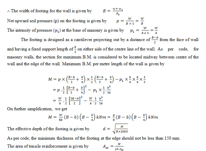
In addition to tensile reinforcement it is necessary to provide longitudinal reinforcement in the footing.
Area of longitudinal reinforcement = 0.15% of sectional area of footing for mild steel reinforcement and 0.12% of sectional area of footing for HYSD bars.
Check for shear: The critical section for shear is considered to be located at a distance of effective depth from the face of the wall.
Check for development length: It should be ensured that the length of the bars provided as tensile reinforcement is not less than beyond the critical section for max. B.M.
Example 29.1 Design a R.C.C. footing for a 300 mm thick brick wall carrying a load of 120 kN per metre length of the wall. The safe bearing capacity of soil is 90 kN/m2. Use M 15 grade of concrete and using HYSD reinforcement.
Solution Design constants :
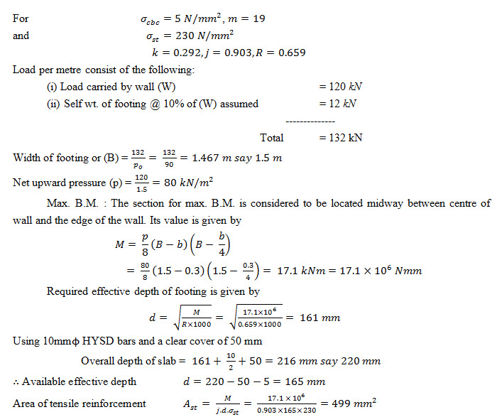
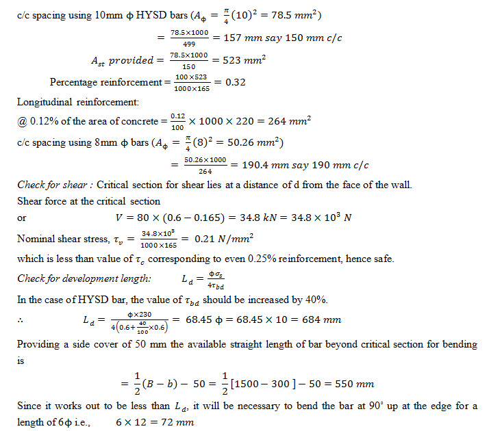
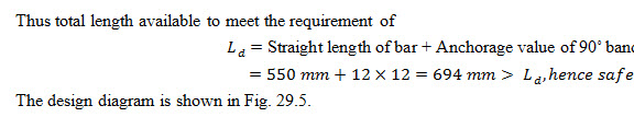
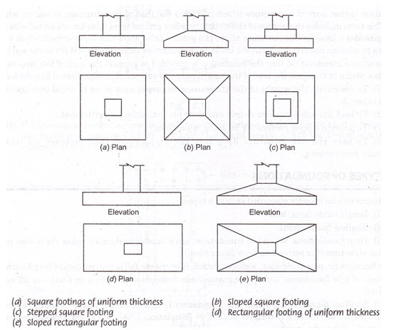
Fig. 29.1 Types of spread footings
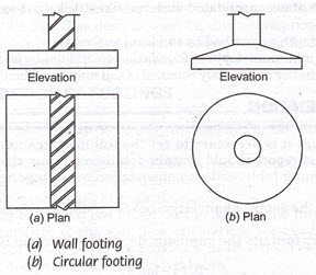
Fig. 29.2 Spread footings
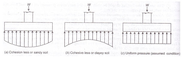
Fig. 29.3 Pressure distribution under footings
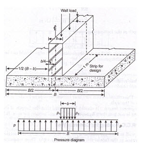
Fig. 29.4 RCC footing for masonry wall
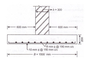
Fig. 29.5 RCC footing for wall (Example 29.1)
Last modified: Thursday, 3 April 2014, 5:57 AM