Site pages
Current course
Participants
General
MODULE 1.
MODULE 2.
MODULE 3.
MODULE 4.
MODULE 5.
MODULE 6.
MODULE 7.
MODULE 8.
MODULE 9.
MODULE 10.
MODULE 11.
MODULE 12.
LESSON 32. Design of RCC Cantilever Retaining Walls
32.1 INTRODUCTION
The different components of the wall are treated as cantilever slab uniformly loaded in the direction of the length of the wall. Hence the wall is designed for one metre length and the same design holds good for the remaining length of the wall. Shear reinforcement is normally not provided in a retaining wall. In case the shear stress at the critical section for any/all of the components of wall works out to be more than permissible shear stress, the thickness of the component should be increased to bring the shear stress within permissible limit. The main reinforcement in stem, toe and heel must be extended in to the base slab, beyond the respective critical section for bending by a distance = \[{L_d}\] . The salient aspects to be considered in the design of each part of the wall are summarized below.
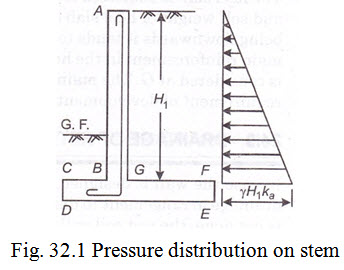
(1) Design of stem: The stem is designed as a vertical cantilever slab fixed at the base. It is subjected to lateral soil pressure. The distribution of pressure along the height of the wall is triangular. Refer the Fig. 32.1. The maximum bending moment occur at junction G. The total lateral pressure acts at \[{H_1}/3\] and it value \[= \frac{1}{2}.{\text{\gamma }}H_1^2.{k_a}.\]
The magnitude of maximum B.M. at G \[= \frac{1}{2}.{\text{\gamma }}H_1^2.{k_a}. \times \frac{{{H_1}}}{3} = \frac{{{\text{\gamma }}H_1^3}}{6}.{k_a}\]
The main reinforcement is placed near the back face of the wall. The reinforcement can be curtailed towards the top of the stem since the bending moment varies as \[H_1^3\] . Distribution reinforcement is provided @ 0.15% of the average area of cross-section. Temperature reinforcement is provided near the front face in the form of vertical and horizontal reinforcement equal in area to distribution reinforcement. The critical section for shear is considered at G. The shear stress at G should be less than permissible shear stress. The stem reinforcement must be extended by a distance = \[{L_d}\] in the base slab to meet the requirement of development length.
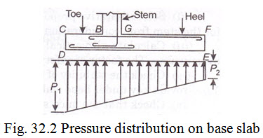
(2) Design of toe slab: The toe slab is designed as a cantilever slab fixed at the front face of the stem i.e., at B. The toe is acted upon by two forces (i) large upward soil reaction and (ii) downward force due to weight of toe slab. Refer the Fig. 32.2.
The net pressure being upwards, it tends to bend the toe upwards so that tension develops on the bottom face. Hence main reinforcement in the toe slab is placed near the bottom face of the slab.
Critical section for shear considered at a distance of effective depth from face of stem B. The main reinforcement must be extended beyond B by a distance = \[{L_d}\] to meet the requirements of development length.
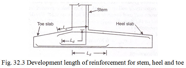
(3) Design of heel slab: This is designed as a cantilever slab fixed at back face of stem at G. The heel slab is subjected to large downward forces to weight of column of earth above the heel slab and self weight of heel slab and small upward force due to upward soil reaction. The net pressure being downwards it tends to bend the slab downwards so that tension develops on top face. Hence main reinforcement in the heel slab is placed near the top face of the slab. Critical section for shear is considered at G. The main reinforcement must be extended beyond G by a distance = \[{L_d}\] , to meet requirement of development length. Fig. 32.3 shows the requirements for development length for main reinforcement for retaining wall components at junction of stem, heel and toe slab.
32.2 DRAINAGE OF RETAINING WALL
In case the wall is designed for dry or moist backfill conditions, it is necessary to make adequate drainage arrangement to discharge the rain water that will percolates within the backfill soil. If this is not done, the wet soil will impose large lateral soil pressure which can endanger the stability of the wall. Drainage of wall is achieved providing weep holes in the stem at suitable intervals say 2 m c/c by vertically and horizontally. The lowest weep hole is kept 300 mm above the ground level on toe side. In order to prevent blockage of the weep holes, a 450 mm thick layer of some filter media (stone chips, gravel, or similar granular material) is placed between the wall right from footing up to the top of stem.
32.3 STEPS TO BE FOLLOWED IN THE DESIGN OF A CANTILEVER RETAINING WALL
(i) Calculate the depth of foundations from Rankine’s formula (if required) and fix total height of the wall.
(ii) Select tentative proportions for the different components of the wall and fix the thickness for the stem from consideration of max. B.M. at its junction with base slab.
(iii) Calculate all vertical and horizontal forces and check the stability of the wall against overturning. The factor of safety should not be less than 2.0.
(iv) Check the stability of the wall against sliding. The factor of safety should not be less than 1.5. Provide key under base slab if necessary.
(v) Check that the max. soil pressure at toe does not exceed the safe bearing capacity of soil.
(vi) Calculate max. B.M. for different wall components based on detail given in Art. 32.1and design the toe and heel slab first. Since the thickness of the toe/heel slab influences the height of stem, the design of the stem should be taken up subsequently. Check the section for shear and development length. Shear reinforcement is not normally used in the wall. The thickness of the components, should be increased to make it safe in shear.
Example 32.1 Design a cantilever type of R.C.C. retaining wall to retain leveled earthen embankment 3m high above ground level. Density of earth is 16000 N/m3 and its angle of repose is 30˚. The safe bearing capacity of soil at a depth of 1m below ground level is 100 kN/m2 . The coefficient of friction between soil and concrete may be taken as 0.55. Use M 15 grade of concrete and mild steel reinforcement in the design.
Solution : Design constants:
For M 15 grade of concrete \[{\sigma _{cbc}} = \frac{{5N}}{{m{m^2}}}\] ; \[m = 19\]
For mild steel reinforcement \[{\sigma _{st}} = 140N/m{m^2}\]
\[k = 0.404,j = 0.865andR = 0.874\]
Co-efficient of active earth pressure
\[{k_a} = \frac{{1 - \sin \phi }}{{1 + \sin \phi }} = \frac{{1 - {\text{sin}}{{30}^{\text{o}}}}}{{1 + {\text{sin}}{{30}^{\text{o}}}}} = \frac{1}{3}\]
Depth of foundation: From Rankine’s formula, minimum depth of foundation \[({D_f})\] is given by
\[{D_f} = \frac{{{p_0}}}{{\text{\gamma }}}{\left( {\frac{{1 - \sin \phi }}{{1 + \sin \phi }}} \right)^2} = \frac{{110 \times {{10}^3}}}{{16000}}{\left( {\frac{{1 - \sin \phi }}{{1 + \sin \phi }}} \right)^2}\]
\[= \frac{{110 \times {{10}^3}}}{{16000}} \times {\left( {\frac{1}{3}} \right)^2} = 0.76m\]
Let us adopt minimum depth of foundation = 1m to ensure that the top of base slab of the wall will remains below the ground.
Total height of (H) of the wall including base slab \[= 3 + 1 = 4m\]
Preliminary dimensions of the wall components:
(i) Width of base slab (b): This may vary between 0.4 H to 0.65 H.
Let us adopt a base width \[= 0.55{\text{}}H\]
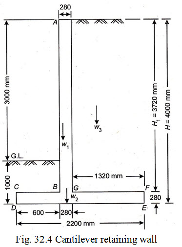
\[b = 0.55 \times 4 = 2.2m\]
(ii) Toe projection: Adopt toe projection \[= b \times \beta\]
where \[\beta= 1 - \frac{{{P_o}}}{{2.2{\text{\gamma }}H}} = 1 - \frac{{100x{{10}^3}}}{{2.2x1600x4}} = 0.29\]
\[b \times \beta= 2.2 \times 0.29 = 0.63msay0.6m\]
(iii) Thickness of base slab: This normally varies from \[\frac{H}{{15}}\] to \[\frac{H}{{10}}\] .
Let us adopt thickness of base slab \[= \frac{H}{{14}} = \frac{4}{{14}} = 0.28m\]
(iv) Thickness of stem: This can be fixed from consideration of max. bending moment.
Clear height of stem wall \[= 4 - 0.28 = 3.72m\]
Consider one metre length of retaining wall
Active earth pressure (P) at any depth to ‘h’ is given by
\[P = \frac{1}{2}.w.{h^2}.\frac{{1 - {\text{sin}}\phi }}{{1 + {\text{sin}}\phi }} = \frac{1}{2}w{h^2}{k_a}\]
For \[h = 3.72m\]
\[P = \frac{1}{2} \times 16000 \times {3.72^2} \times \frac{1}{3} = 36900N\]
acting at \[\frac{{3.72}}{3}\] m from heel slab top.
Max. BM. at G \[M = 36700 \times \frac{{3.72}}{3}\]
\[= 45760Nm = 45760 \times {10^3}Nmm\]
\[d = \sqrt {\frac{{45760 \times {{10}^3}}}{{0.874 \times {{10}^3}}}}= 229mm\]
Since the stem wall is in contact with earth
Provide clear cover \[= 40mm\]
Assuming 16 mm \[\phi\] bars, adopt overall thickness of stem
\[= 229 + 40 + \frac{{16}}{2} = 227mmsay280mm\]
Available \[d = 280 - 40 - 8 = 232mm\]
Check for shear : \[{\tau _v} = \frac{V}{{bd}} = \frac{{36900}}{{1000x232}}\]
\[= 0.16N/m{m^2} < {\tau _b}\]
\[< 0.22N/m{m^2}\] , hence OK.
The height of the stem is comparatively small and as such it will not be advantageous to reduce the thickness at top. The saving made in the quantity of concrete due to tapering of stem will be offset by the increased cost of providing inclined shuttering. As such the thickness of stem will be maintained as 280 mm uniformly throughout its height. Since the thickness of toe and slab influences the height of stem, the final stem thickness and its design should be taken after the design of toe and heel slab. The preliminary dimensions of different components of the wall are shown in Fig. 32.4.
Check for stability of the wall: Before proceeding with the design further, it is necessary to ascertain the stability of the wall with the preliminary dimensions of the base width.
Following checks are made in this connection:
(a) Check against overturning
(b) Check against sliding
(c) Check against max. pressure at toe
Consider one metre length of the retaining wall.
(a) Check against overturning : The various loads and their moments about the toe slab(at D) are tabulated as under.
|
S.No |
Description of load |
Magnitude of load in Newton (N) |
Dist. of C.G D in metres (m) |
Moment about D in (Nm) |
|
1. |
Wt. of stem wall (or W1 ) |
0.28 x 3.72 x 25000 = 26040 |
0.6 + 0.28/2 = 0.74 |
19270 |
|
2. |
Wt. of base slab (or W2 ) |
2.2 x 0.28 x 25000 = 15400 |
2.2 / 2 = 1.10 |
16940 |
|
3. |
Wt. of earthfill over heel slab(or W3) |
1.32 x 372 x 16000 = 78570 |
1.32 / 2 + 0.28 + 0.60 = 1.54 |
121000 |
|
|
|
∑W = 120010 N |
|
MR = 157210 |
Total horizontal earth pressure on the full height of the retaining wall tending to overturn the wall
\[P = \frac{1}{2}w{H^2}\frac{{1 - {\text{sin}}\phi }}{{1 + {\text{sin}}\phi }} = \frac{1}{2} \times 16000 \times {4^2} \times \frac{1}{3} = 42667N\]
acting at \[\frac{4}{3}\] from D
Total overturning moment \[{M_0} = 42667 \times \frac{4}{3} = 56890Nm\]
Total stabilizing moment \[{M_R} = 157210Nm\]
Factor of safety against overturning = ![]() , hence safe.
, hence safe.
(b) Check against stiding. Total horizontal force tending to slide the wall
\[P = \frac{1}{2}w{H^2}{k_a} = 42667N\]
Total force opposing sliding \[= {\text{\mu }} \times {\text{\Sigma }}W = 0.55 \times 120010 = 66010N\]
Factor of safety against sliding ![]() , hence safe.
, hence safe.
(c) Check against max. pressure at toe. Net moment or algebraic sum of moments about D
\[= {M_R} - {M_o} = 157210 - 56890 = 100320Nm\]
Let \[\bar x\] be the distance from toe (D) at which the resultant reaction acts
\[\bar x = \frac{{100320}}{{120010}} = 0.836{\text{m}}\]
Equation (e) \[= \frac{b}{2} - \bar x = \frac{{2.2}}{2} - 0.836\]
![]() , hence O.K.
, hence O.K.
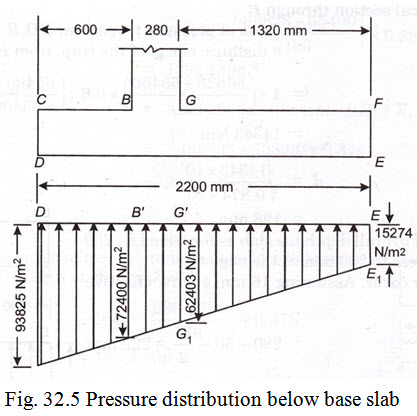
Max. pressure at toe (D) and minimum pressure in heel (E) is given by the formula
\[p = \frac{{{\text{\Sigma }}W}}{b}\left( {1 \pm \frac{{6e}}{b}} \right)\]
\[{P_{max}}attoe\left( D \right)\] \[= \frac{{{\text{\Sigma }}W}}{b}\left( {1 + \frac{{6.e}}{b}} \right) = \frac{{120010}}{{2.2}}\left( {1 + \frac{{6 \times 0.264}}{{2.2}}} \right)\]
\[ = \frac{{{\text{\Sigma }}W}}{b}\left( {1 + \frac{{6.e}}{b}} \right) = \frac{{120010}}{{2.2}}\left( {1 + \frac{{6 \times 0.264}}{{2.2}}} \right)\] , hence safe.
\[{P_{max}}atheel\left( E \right)\] \[= \frac{{{\text{\Sigma }}W}}{b}\left( {1 - \frac{{6.e}}{{2.2}}} \right) = \frac{{120010}}{{2.2}}\left( {1 - \frac{{6 \times 0.264}}{{2.2}}} \right)\]
\[15274N/{m^2}\]
The intensity of pressure distribution between toe (D) and heel (E) being linear, pressure at junction of stem with toe slab
\[= 15274 + \left( {\frac{{93823 - 15274}}{{2.2}}} \right) \times \left( {2.2 - 0.6} \right)\]
\[= 72400N/{m^2}\]
and pressure at the junction of stem with heel slab
\[= 15274 + \left( {\frac{{93823 - 15274}}{{2.2}}} \right) \times 1.32\]
\[= 62403N/{m^2}\]
The pressure distributions at various points are given in Fig. 32.5. Since the wall with assumed base width is found to be safe from stability consideration. We can now go ahead with the design of different components of the wall i.e., toe slab, heel slab and the stem.
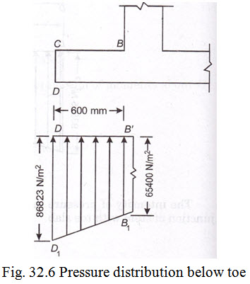
(1) Design of toe slab : Neglecting the weight of soil on the toe slab, the forces acting on toe slab are :
(i) Upward soil reaction varying from 93823 N/m2 at (D) to 72400 N/m2 at (B).
(ii) Downward pressure due to self weight of toe slab = 0.28 x 25000 = 7000 N/m2
Net upward pressure under (D) = 93823 - 7000 = 86823 N/m2
and Net upward pressure under (B) = 72400 - 7000 = 65400 N/m2
Refer Fig. 32.6.
Consider 1 m length of wall:
Max. B.M. at a vertical section through B = Area of pressure trapezium DD1B'B1 x distance of c.g. of the trap, from B'B1
\[= 1 \times \left( {\frac{{86823 + 65400}}{2}} \right) \times 0.6 \times \left( {\frac{{65400 + 2 \times 86823}}{{65400 + 86823}}} \right) \times \frac{{0.6}}{3} = 14343Nm\]
\[d = \sqrt {\frac{{14343 \times {{10}^3}}}{{0.874 \times {{10}^3}}}}= 128mm\]
However adopt same overall depth toe slab as for stem i.e., 280mm at B. Reduce thickness to 200 mm at the edge C. Provide 50 mm clear cover.
Assuming 16mm \[\phi\] bars, effective depth of toe slab \[= 280 - 50 - \frac{{16}}{2} = 222mm\]
\[{A_{st}} = \frac{M}{{j.d.{\sigma _{st}}}} = \frac{{14343 \times {{10}^3}}}{{0.865 \times 222 \times 140}} = 533m{m^2}\]
Spacing of 16mm \[\phi\] bars (A\[\phi\] = 201mm2) \[= \frac{{201 \times 1000}}{{533}} = 377mmsay370mm\]
However, situations where toe projections as well as the thickness of the base slabe are less, the requirement of area of reinforcement for the toe slab can be adequately met by extending the main reinforcement of the stem in to the slab. Such extension of stem bars becomes essential to meet the requirement of development length of the stem reinforcement as well. As can be seen from the design of stem, 16mm \[\phi\] bars @ 120 mm c/c are available to meet the requirement of toe reinforcement
Distribution reinforcement:
\[= \frac{{0.15}}{{100}} \times \left( {\frac{{280 + 200}}{2}} \right) \times 1000 = 360m{m^2}\]
Spacing of 10mm \[\phi\] bars \[({A_{st}} = 79m{m^2})\] \[\frac{{79 \times 1000}}{{360}} = 219mmsay200mmc/c\]
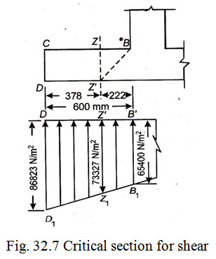
Check for shear:
The critical section for shear (section Z – Z’) is considered at a distance “d” from the front face of the stem wall. Refer Fig. 32.7.
From the geometry of net pressure diagram, pressure ordinate at section Z-Z’ is given by
\[= 65400 + \left( {\frac{{86823 - 65400}}{{0.6}}} \right)x0.222 = 73327N/{m^2}\]
S.F. at section Z-Z’ = Area of pressure trap. DD1Z'Z1
\[= \frac{1}{2}\left( {86823 + 73323} \right) \times 0.378 = 30268N\]
\[{\tau _v} = \frac{V}{{bd}}\]
Assuming the thickness of toe slab to be reduced to 200 mm at edges, effective depth of slab at section Z-Z’
\[= 200 + \left( {\frac{{280 - 200}}{{0.6}}} \right) \times 0.378 = 192.4mm\]
\[{\tau _v} = \frac{{30268}}{{1000 \times 192.4}} = 0.16N/m{m^2} < 0.22N/m{m^2}\] , hence safe.
2. Design of heel slab: From the pressure diagram shown in Fig. 32.5, it can be seen that the upward pressure on the heel slab varies from 62403 N/m2 at G to 15274 N/m2 at E. In addition to the upward pressure the heel slab is also subjected to the following uniform downward pressure.
(i) Downward pressure due to self wt. of heel slab = 0.28 x 1.32 x 25000 = 9240N
Acting at \[\frac{{1.32}}{2} = 0.66m\] from G.
(ii)Downward pressure due to self wt. of earthfill on heel slab
= 1.32 x 3.72 x 16000 = 78566N
acting at 0.66 m from G.
Total upward soil pressure = Area of pressure trap. EE1G'G1
\[= \frac{1}{2}\left( {62403 + 15274} \right)x1.32 = 51267N\]
acting at \[\left( {\frac{{62403 + 2x15274}}{{62403 + 15274}}} \right) \times \frac{{1.32}}{3}\] = 0.526 m from G.
Net B.M. at G = B.M. due to downward pressure - B.M. due to upward pressure
= 9240 x 0.66 + 78566 x 0.66 - 51267 x 0.526
= 6098 + 51854 - 26966
= 30986 x 103 Nmm
\[d = \sqrt {\frac{{30986 \times {{10}^3}}}{{0.874 \times {{10}^3}}}}= 188mm\]
However adopt same overall depth as far stem i.e., 280mm at G. Reduce, the thickness to 200 mm at the edges. Provide 50 mm clear cover.
Assuming 16mm \[\phi\] bars, available effective cover = \[280 - 50 - \frac{{16}}{2} = 222mm\]
\[{A_{st}} = \frac{{30986 \times {{10}^3}}}{{0.865 \times 222 \times 140}} = 1153m{m^2}\]
Spacing of 16mm \[\phi\] bars ( A\[\phi\] = 201mm2 ) \[= \frac{{201}}{{1153}} \times 1000 = 174mmsay170mmc/c\]
Distribution reinforcement :
Same as far toe slab i.e., 10 mm \[\phi\] bars @ 200 mm c/c
The main reinforcement of the heel should be carried into the toe through a distance equal to
\[{L_d} = \frac{{\phi {{\text{\sigma }}_{{\text{st}}}}}}{{4{\tau _{bd}}}}= \frac{{\phi{\text{}} \times {\text{}}140}}{{4 \times 0.6}}= 58\phi= 58 \times 16 = 930mmtotheleftofG.\]
Check for shear:
Max. S.F. in heel slab occurs at G. Its value being given by:
V= Total downward pressure - Total upward pressure
= 9240 + 78566 - 51267 = 36532 N
\[{\tau _v} = \frac{V}{{bd}} = \frac{{36539}}{{222x1000}} = 0.16N/m{m^2}\]
< minimum value of \[{\tau _c}\] , hence safe.
3. Design of stem slab: Since the base slab is 280 mm thick, clear height (H1) of the stem above base slab \[= 4.00 - 0.28 = 3.72m\]
Max. B.M. at G \[= \frac{{w{h^3}}}{6}.\frac{{1--\sin \phi }}{{1 + \sin \phi }} = \frac{{16000 \times {{3.72}^3}}}{6} \times \frac{1}{3} = 45759Nm\]
\[= 45759 \times {10^3}Nm\]
\[D = 280andd = 280 - 40 - \frac{{16}}{2} = 232mm\]
\[{A_{st}} = \frac{{45759 \times {{10}^3}}}{{0.865 \times 232 \times 140}} = 1628m{m^2}\]
Spacing, using 16 mm \[\phi\] bars \[\left( {{A_\phi } = 201m{m^2}} \right)\] \[= \frac{{201}}{{1628}} \times 1000 = 123mmsay120mm\]
Hence provide 16 mm \[\phi\] bars @ 120 mm c/c
Extend the bars for a distance of \[{L_d} = 58\phi= 58{\text{}} \times {\text{}}16 = 930{\text{mm}}\]
beyond G into the bottom face of toe slab.
Beyond the distance of 930 mm alternate bars could be curtailed in the region of toe. However, since the toe projection is only 600 mm, it is proposed not to curtail the bars and continuous 16 mm \[\phi\] bars @ 120 mm c/c in the full length of toe.
Curailment of reinforcement in stem wall :
Since the stem is of uniform thickness. Max. B.M. will get reduced to nearly half at a distance of 0.80 x 3.72 = 2.976 say 2.9m below top
BM. at 2.9 in below top \[= \frac{{16000 \times {{2.9}^3}}}{6} \times \frac{1}{3} = 21679Nm\]
Since this is less than \[\frac{1}{2}\] of max. B.M. at G, alternate bars can be curtailed at a depth of 2.9m below top. However as per rules the bars to be curtailed shall extend by a distance equal to 12 x dia. of bars i.e., 12 x 16 = 192 mm or effective depth of the slab i.e., 232 mm whenever is more.
Hence alternate bars shall actually be curtailed at 2.9 – 0.23 = 2.67 m from top. The spacing of bars beyond this point will be 2 120 = 240 mm c/c.
Distribution reinforcement:
\[= \frac{{0.15}}{{100}} \times 280 \times 100 = 420m{m^2}\]
Area of reinforcement on each face \[= 420 \times \frac{1}{2} = 210m{m^2}\]
c/c spacing of 10mm \[\phi\] bars \[= \frac{{79 \times 1000}}{{210}} = 376mmsay370mmc/c\]
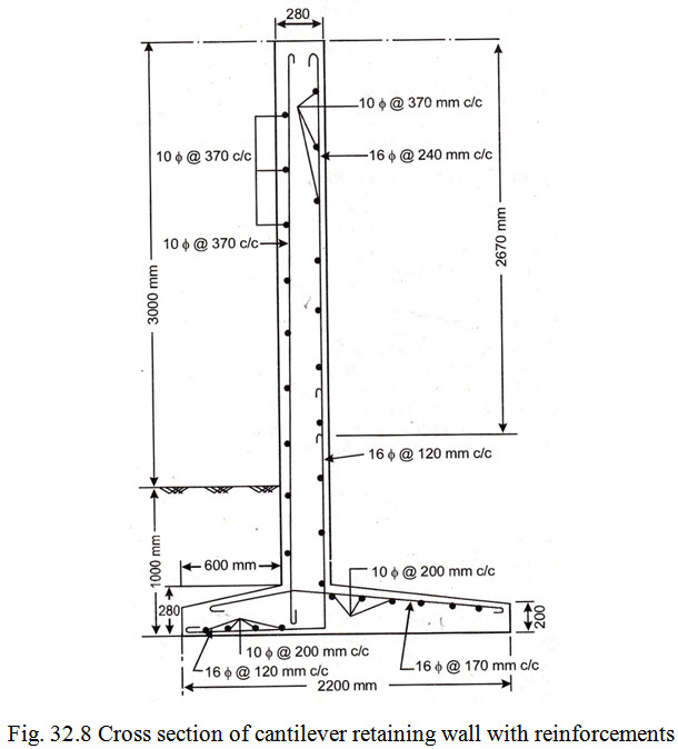
Hence provide 10mm \[\phi\] bars @ 370 mm c/c both ways at the outer face (exposed) of the stem wall as temperature reinforcement and 10mm \[\phi\] bars @ 370 mm c/c as horizontal reinforcement on inner face of wall.
Check for shear:
Max. S.F. occur at section through G its value being given by
\[V = \frac{{w{h^2}}}{2}.\frac{{1 - sin\phi }}{{1 + sin\phi }} = \frac{{16000 \times {{3.72}^2}}}{2} \times \frac{1}{3} = 36902N\]
![]() Hence safe.
Hence safe.
The design diagram is shown in Fig. 32.8.
Last modified: Friday, 4 April 2014, 10:40 AM