Site pages
Current course
Participants
General
MODULE 1.
MODULE 2.
MODULE 3.
MODULE 4.
MODULE 5.
MODULE 6.
MODULE 7.
MODULE 8.
MODULE 9.
MODULE 10.
MODULE 11.
MODULE 12.
LESSON 30. Design of Isolated Column Footing
30.1 INTRODUCTION
The load from an isolated column may be distributed on the bearing strata by providing a square, rectangular or circular flooring. The footing may be in the form of a flat slab of uniform thickness; it may be stepped or it may be sloped at the edges. The isolated column footing can therefore be subdivided into the following categories.
-
Square footing of uniform thickness
-
Rectangular footing of uniform thickness
-
Square sloped footing
-
Rectangular sloped footing
-
Circular footing.
Design of different categories of isolated footings has been dealt separately in the following articles.
30.2 SQUARE FOOTING OF UNIFORM THICKNESS
Let ‘b’ be the one side of the square column and B be the one side of the square footing.
Area required for the footing \[= B \times B = \frac{{W + {W_1}}}{{{p_0}}}\]
or \[B = \sqrt {\frac{{W + {W_1}}}{{{p_0}}}}\]
and the net upward pressure on the footing \[p = \frac{W}{{{B^2}}}\]
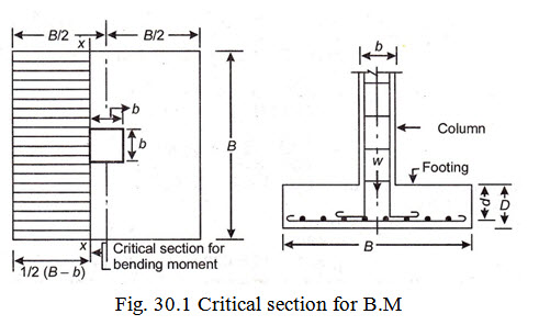
(a) Bending moment : Critical section for max. B.M. is taken at the face of the column or pedestal i.e., section X-X.
The value of max. B.M. at section X –X is given by
M= moment of the forces over the entire area on one side of the plane
\[= p \times B \times \left( {\frac{{B - b}}{2}} \right) \times \left( {\frac{{B - b}}{4}} \right) = p.\frac{B}{8}{\left( {B - b} \right)^2}\]
(b) To fix depth of the footing: The effective depth of the footing shall be greater of the following .
1. Depth from consideration of max. B.M.: This is given by formula \[d = \sqrt {\frac{M}{{RxB}}}\]
2. Depth from consideration of shear: The effective depth obtained from B.M. consideration is to be checked for adequacy in shear. As per IS: 456-1978, the footing slab is required to be checked for following two types of shear.
(i) Check for one way shear
(ii) Check for two way shear or punching shear
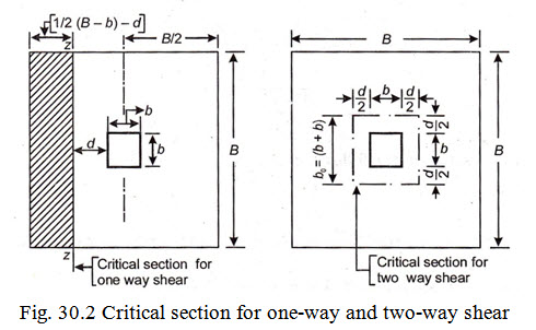
(i) Check for one way shear: Critical for one way shear is considered at at a distance ‘d’ from the face of the column or pedestal as shown in Fig. 30.1.
The magnitude of shear force at the critical section is given by
\[V = p \times B \times \left[ {\frac{1}{2}\left( {B - b} \right) - d} \right]\]
Nominal shear stress, \[{\tau _v} = \frac{V}{{B \times d}}\]
The value of \[{\tau _v}\] should work out to be less than or equal to \[k.{\tau _c}.\] For working out \[{\tau _c}\] it is assumed that the section of the footing is a balanced one having percentage of reinforcement
\[p = \frac{{k.{\sigma _{cbc}}}}{{2{\sigma _{st}}}}x100\]
For M 15 grade of concrete and mild steel reinforcement \[{\tau _c}\] works out to be \[= 0.33N/m{m^2}\] . (From Table 22.1). Similarly from Table 22.2, it can be seen that the value of k for slabs 300 mm or more in thickness =1. Hence the value of \[k.{\tau _c}\] in such a case works out to \[1 \times 0.33N/m{m^2} = 0.33N/m{m^2}\] . In case the value of \[{\tau _v}\] should work out to be more than \[k.{\tau _c}\] it becomes necessary to revise the depth. The revised depth of the footing can be obtained by equating
\[{\tau _v} = k.{\tau _c}\]
or \[\frac{V}{{B \times d}} = k.{\tau _c}\]
or \[d = \frac{V}{{B \times k.{\tau _c}}}\]
(ii) Check for two way shear: The critical section for two-way shear (also known as punching shear) is considered at a distance d/2 from the periphery of the face of the column or pedestal, as shown in Fig. 30.2
The magnitude of shear force V’ at the critical section is given by
\[V' = p\left[ {{B^2} - {{\left( {b + d} \right)}^2}} \right]\]
Nominal shear stress at the critical section \[\tau {'_v} = \frac{{V'}}{{{b_0} \times d}}\]
where ![]()
The value of \[\tau {'_v}\] should work out to be less than \[{k_s}x\tau {'_c}\]
where \[{k_s} = \left( {0.5 + {\beta _c}} \right)\] but not greater than 1, \[{\beta _c}\] being the ratio of short side to long side of the column
and \[\tau {'_c} = 0.16\sqrt {{f_{ck}}}\]
In normal case \[{k_s}\] will works out to be more than 1 and as such, its value is restricted to1. The value of \[\tau {'_c}\] for M 15 grade of concrete = 0.16 \[\sqrt {15}\] = 0.62 N/mm2.
In case the value of \[\tau {'_v}\] works out to be more than \[{k_s}.\tau {'_c}\] it becomes necessary to revise the depth. The revised depth of the footing can be obtained by equating \[\tau {'_v} = k.\tau {'_c}\]
or \[\frac{V}{{{b_0} \times d}} = {k_s}.\tau {'_c}\]
or \[d = \frac{{V'}}{{{b_0} \times {k_s}.{\tau _c}'}}\]
Adopt higher of the above values of “d” in design.
Since the reinforcing bars are provided by placing bars at right angles to each other in the form of a mesh, the overall depth (D) of the footing is fixed as explained below.
Let the dia. of the reinforcing bar = \[\phi\] and the clear cover for the bottom layer of bars = 50 mm. Since the value of “d” found above is applicable to top layer of bars, overall depth (D) of the footing is given by
\[D = \left( {d + \phi+ {\text{}}\frac{1}{2}\phi+ 50} \right){\text{mm}}\]
(a) Area of reinforcement : Area of reinforcement in each direction is given by
\[{A_{st}} = \frac{M}{{j.d.{\sigma _{st}}}}\]
The reinforcement is uniformly distributed over the entire width of the footing in each direction.
(b) Check for development length: The development length is checked at a section along the face of the column i.e., the section for maximum B.M.
Example 30.1 Design a square footing of uniform thickness for an axially load column of 500 mm x 500 mm in size transmitting a load of 600 kN. The safe bearing capacity of soil is 150 kN/sq m. Use M 20 grade of concrete and HYSD reinforcement.
Solution Design constants.
For HYSD \[{\sigma _{st}} = 230N/m{m^2}\]
For M 20 grade of concrete \[{\sigma _{cbc}} = 7N/m{m^2}\]
\[m = \frac{{280}}{{3.{\sigma _{cbc}}}} = \frac{{280}}{{3 \times 7}} = 13.33\]
\[k = \frac{{m.{\sigma _{cbc}}}}{{m.{\sigma _{cbc}} + {\sigma _{st}}}} = \frac{{13.33 \times 7}}{{13.33 \times 7 + 230}} = 0.288\]
\[j = 1 - \frac{{0.288}}{3} = 0.904\]
and \[R = \frac{1}{2}{\sigma _{cbc}}.j.k = \frac{1}{2} \times 7 \times 0.904 \times 0.288 = 0.91\]
Safe bearing capacity of soil = \[{p_o}\] = 150 kN/sq.m.
Required area of footing (A) \[= \frac{{660}}{{150}} = 4.4sq.m\]
Let B, be one side of the square footing,
\[B \times B = A = 4.4sq.m\] or \[B = \sqrt {4.4}= 2.1m\]
Adopt footing of size 2.1 m x 2.1 m.
Net upward pressure (p) : \[= \frac{W}{{BxB}} = \frac{{600}}{{2.1 \times 2.1}} = 136kN/{m^2}\]
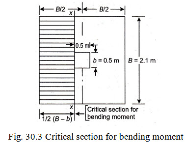
(a) Bending moment: Critical section for bending moment is considered at the face of the column i.e., section X-X as shown in the Fig. 30.3. The magnitude of B.M. is given by
\[M = P.\frac{B}{8}{\left( {B - b} \right)^2}\]
\[= 136 \times \frac{{2.1}}{8}{\left( {2.1 - 0.5} \right)^2}\]
\[= 91.4kNm = 91.4 \times {10^6}Nmm.\]
(b) To fix depth of footing
1. Depth from consideration of max. B.M. : This is given by
\[d = \sqrt {\frac{M}{{R.B}}}= \sqrt {\frac{{91.4 \times {{10}^6}}}{{0.91 \times 2100}}}= 219mm\]
2. Depth from consideration of shear: Adequacy of the above depth is to be checked from consideration of shear.
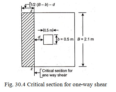
(i) Check for one-way shear: The critical section for one-way shear is considered at a distance ‘d’ from the face of the column. Refer Fig. 30.4.
The magnitude of shear force V at the critical section is given by
\[V = p \times B \times \left[ {\frac{1}{2}\left( {B - b} \right) - d} \right]\]
\[= 136 \times 2.1\left[ {\frac{1}{2}\left( {2.1 - 0.5} \right) - 0.219} \right] = 166kN\]
\[{\tau _v} = \frac{V}{{B \times d}} = \frac{{166 \times {{10}^3}}}{{2.1 \times 1000 \times 219}} = 0.36N/m{m^2}\]
This should be less than or equal to \[k{\tau _c}\]
For a balanced section percentage of reinforcement
\[= \frac{{k.{\sigma _{cbc}}}}{{2 \times {\sigma _{st}}}} \times 100 = \frac{{0.228 \times 7 \times 100}}{{2 \times 230}} = 0.44\%\]
Corresponding value of \[{\tau _c}\] as obtained from Table 22.1 for M 20 grade of concrete
\[{\tau _c} = 0.22 + \frac{{\left( {0.30 - 0.22} \right)}}{{0.25}}\left( {0.44 - 0.250} \right) = 0.28N/m{m^2}\]
\[k = 1\]
\[kx{\tau _c} = 1 \times 0.28\frac{N}{{m{m^2}}} = 0.28N/m{m^2}\]
Since \[{\tau _v} > k{\tau _c}\] , it will be necessary to revise the depth
Revision. In the limiting case \[{\tau _v} = k.{\tau _c}\]
To find the value of “d” so that
\[{\tau _v} = k.{\tau _c}\]
\[{\tau _v} = \frac{V}{{bd}}\]
or \[{\tau _v} = \frac{{166 \times {{10}^2}}}{{2.1 \times 1000 \times d}} = k.{\tau _v} = 0.28\]
\[d = \frac{{166 \times {{10}^2}}}{{2.1 \times 1000 \times 0.28}} = 280mm\]
Adopt revised value of d = 280 mm for check for two-way shear.
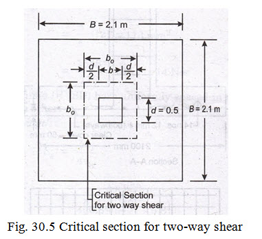
(ii) Check for two-way shear: The critical section for two-way shear or punching shear is considered at a distance of d/2 from face of column. Refer Fig. 30.5.
The net S.F. at the critical section is given by
\[V = p\left[ {{B^2} - {{\left( {b + d} \right)}^2}} \right]\]
\[= 136\left[ {{{\left( {21} \right)}^2} - {{\left( {0.5 + 0.280} \right)}^2}} \right] = 517kN\]
Nominal shear stress at the critical section \[{\tau _v} = \frac{{V'}}{{{b_o} \times d}}\]
\[{b_o} = 4\left( {b + d} \right) = 4\left( {0.5 + 0.280} \right) = 3.128m = 3.128 \times {10^3}mm\]
\[d = 0.280mm\]
\[{\tau _v} = \frac{{V'}}{{{b_o} \times d}} = \frac{{517 \times {{10}^3}}}{{3.128 \times {{10}^3} \times 280}} = 0.592N/m{m^2}\]
This should be less than or \[= {k_s}.{\tau _c}\]
\[= \left( {0.5 + {\beta _c}} \right) \times 0.16\sqrt {{f_{ck}}}\]
\[= 1 \times 0.16\sqrt {20}= 0.715N/m{m^2}\]
Since \[{\tau _v} < {k_s}{\tau _c}\] , hence safe.
Thus the effective depth of footing (i.e. d = 280 mm) is governed by requirement of one-way shear. Overall depth, assuming 12 mm \[\phi\] bars (placed one over the other in two directions at right angles) and clear cover of 50 mm
\[D = 280 + 12 + \frac{{12}}{2} + 50 = 348mmsay350mm\]
Available effective depth for bottom layer of bars = 350 - 50 - 12/2 = 294 mm
and “d” for top layer = 294 -12 = 282 mm.
(c) Area of steel reinforcement in each direction is given by
\[{A_{st}} = \frac{M}{{j.d.{\sigma _{st}}}} = \frac{{91.4 \times {{10}^6}}}{{0.904 \times 282 \times 230}} = 1560m{m^2}\]
Area of one 12 mm \[\phi\] bars (A\[\phi\] ) = \[\frac{\pi }{4}.{\left( {12} \right)^2} = 113m{m^2}\]
No. of bars required \[= \frac{{1548}}{{113}} = 13.7say14Nos\]
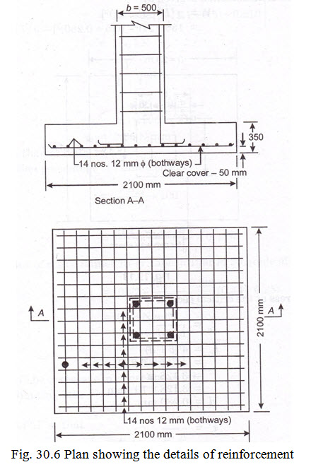
Hence provide 14 Nos 12 mm \[\phi\] (HYSD) bars uniformly spaced in the width of 2.1 m in each direction at right angles to each other.
(d) Check for development length:
\[{L_d} = \frac{{\phi {\sigma _s}}}{{4{\tau _{bd}}}} = \frac{{\phi {\text{}} \times {\text{}}230}}{{4\left( {0.8 + \frac{{40}}{{1000}} \times 0.8} \right)}} = 51.3\phi= 51.3 \times 12 = 616say620mm\]
Providing side cover of 60 mm length of the bar available beyond critical section for B.M.
\[= \frac{1}{2}\left( {B - b} \right) - 60 = \frac{1}{2}\left( {2100 - 500} \right) - 60 = 740mm\]
Which is more than \[{L_d}\] , hence safe. Fig. 30.6 shows the arrangement of reinforcement.
Last modified: Thursday, 3 April 2014, 9:29 AM