Site pages
Current course
Participants
General
Module 1. Hydraulic Basics
Module 2. Hydraulic Systems
MODULE 3.
MODULE 4.
MODULE 5.
MODULE 6.
MODULE 7.
MODULE 8.
LESSON 3. PASCAL’S LAW, FLOW, ENERGY, WORK AND POWER
3.1 INTRODUCTION
Hydraulics plays a significant role in the industrial and agricultural sectors. Hydraulic devices are perhaps amongst the greatest inventions which help human beings in performing complicated and heavy tasks. It is quite wonderful that how a small jack can lift tons and tons of weight with just the pressing of a handle or a hydraulic press can easily cut thick metal sheets. In a tractor or other automobiles hydraulic brake stop a vehicle by overcoming huge momentum of the vehicle using force applied by the driver on brake pedal. All these tasks are possible due to certain principles of hydraulic theory. The fundamental principle of hydraulics was discovered by Blaise Pascal, a French mathematician in 17th century. The law is known as Pascal’s law or principle of transmission of fluid-pressure.
3.2 Pascal’s Law
Pascal’s law states that that pressure exerted anywhere in a confined incompressible fluid is transmitted equally in all directions with equal force on equal areas and acts normal to the surface. The law is illustrated in Fig. 3.1. A force of ‘P’ kgf is exerted on a piston having cross sectional area of ‘A’ cm2. This results in a pressure of magnitude ‘P/A’ kgf/cm2 act on the liquid exactly underneath the piston. Since the liquid is confined, the same pressure is transmitted throughout the liquid and acts on all the surfaces normally with equal magnitude i.e. ‘P/A’ kgf/cm2.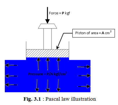
3.3 Application of Pascal’s Law
The principle of Pascal’s law was successfully applied by an English Engineer Mr. Joseph Bramah in 1795 to develop a hydraulic press, in which by applying a small input force a large output force was generated. The Bramah’s press principle may be understood by considering the two piston system shown in Fig. 3.2. A force of 100 kilogram is applied on the smaller cylinder having cross-sectional area of 1 cm2. This creates a pressure of 100 kg/cm2 in the liquid under the cylinder. According to Pascal's Law, this pressure is transmitted undiminished throughout the fluid acting normal in every direction. The 100 kg/cm2 pressure acts on the larger diameter piston having an area of 5 cm2. This results in a force of 100 kg/cm2 x 5 cm2 i.e. 500 kg acting perpendicularly on the piston. Thus the 500 kg force applied on the larger piston in the downward direction is balanced by the 500 kg force on the piston due to fluid pressure in the upward direction. Thus the applied force has been multiplied 5 times – a mechanical advantage of 5 to 1.
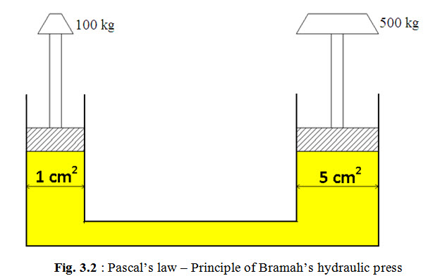
Similarly, the distance moved by larger piston due to movement of smaller piston, in Fig. 3.2, can also be determined. Since hydraulic oil is incompressible, if the small piston moves down it displaces a volume of oil equal to the product of cross-sectional area of the cylinder and the distance traveled by the piston. For example, if the smaller piston is pushed down through a distance of 10 cm it will displace 1 cm2 x 10 cm i.e. 10 cm3 of oil. This will cause the larger piston to move up through a distance equal to 2 cm i.e. displaced oil volume of 10 cm3 divided by larger cylinder area of 5 cm2. Thus it can be observed that for forces F1 and F2 acting on two cylinders undergoing displacements d1 and d2:
F1 x d1 = F2 x d2 (3.1)
Since the product of force and displacement is the work done, Equation 3.1 shows that work done by external force on the system is equal to the work done by the system.
3.4 Flow
Fluid flows from high pressure point to low pressure point. Fluid can be forced to flow from low pressure to high pressure by using a pump. In a hydraulic system, a pump is used to produce oil flow in the system. Flow can be measured in terms of velocity and flow rate.
3.5 Velocity
Velocity of a fluid is the mean speed with which fluid particles move past a given point in unit time. It is usually measured in metre per second (ms-1). Flow velocity is of prime importance in design of hydraulic systems as the pipes and hoses are sized according to velocity requirement.
3.6 Flow Rate
Flow rate of a fluid is the volume of fluid moving past a given point in unit time. It is usually measured in litre per second (l/s) or cubic centimeter per second (cusec). Flow rate determines the speed at which a load moves and therefore it is an important factor for power calculations.
3.7 Relationship between Flow Rate and Velocity
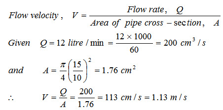
Flow rate through a pipe is equal to product of flow velocity through the pipe and cross-sectional area of the pipe. The following example illustrates this relationship.
Example: Oil flows through a hydraulic pipe of 15 mm diameter at a flow rate of 12 litre per minute. Find the flow velocity.
Solution:
Last modified: Friday, 14 March 2014, 10:49 AM