Site pages
Current course
Participants
General
Module 1. Hydraulic Basics
Module 2. Hydraulic Systems
MODULE 3.
MODULE 4.
MODULE 5.
MODULE 6.
MODULE 7.
MODULE 8.
LESSON 5. PASCAL’S LAW, FLOW, ENERGY, WORK AND POWER
5.1 INTRODUCTION
Hydraulic devices are concerned with flow of liquid in enclosed paths such as pipes, tubes, valves, actuators etc. Flow can be quantified in terms of volumetric flow rate and mass flow rates. Flow can be classified as steady flow and unsteady flow based upon state of conditions at a point with respect to time. Further flow may be classified as laminar flow and turbulent flow based upon flow pattern.
5.2 Volumetric Flow
Volumetric flow rate is the volume of fluid moving past a given point in unit time. It can be calculated as the product of average flow velocity and area of cross-section of the path. It is usually measured in litre per second (l/s) or cubic centimeter per second (cusec).
Volumetric flow rate, V = v.A, cm3/s (5.1)
Where, ‘v’ is the velocity in cm/s and ‘A’ is area of pipe cross-section in cm2.
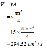
Example: Calculate the volumetric flow rate of a liquid flowing with an average velocity of 15 cm/s in a pipe of diameter 5 cm.
Solution:
5.3 Mass Flow
Mass flow rate can be defined as the measure of the mass of fluid passing through a point in the system per unit time. It is equal to the product of density of the fluid and its volumetric flow rate.
Mass flow rate, M = rV gm3/s (5.2)
Where, ‘ρ’ is the density in gm/cm3 and ‘V’ is volumetric flow rate in cm3/s.
Example: Calculate the mass flow rate of a liquid flowing with an average velocity of 15 cm/s in a pipe of diameter 5 cm. Density of the liquid is 60 gm/cc.
Solution: Volumetric flow rate,
Mass flow rate = ρV
= 60 X 294.52 = 17,671.2 gm/cc.
5.4 Steady and Unsteady Flow
In steady flow, fluid properties like pressure, temperature and velocity at point in the system do not change with time. In the steady state flow rate there is no mass accumulation in the system or component.
Unsteady flow is a transient phenomenon which may become a steady flow or zero flow with time. For example, when a valve is opened suddenly, liquid flow into the pipe is unsteady which become steady with time. Similarly, when a valve is suddenly closed at the discharge end of a pipe, there will be fluctuations in both velocity and pressure in the pipe before the flow becomes zero in the pipe.
5.5 Laminar and Turbulent Flow
When a fluid is flowing through a pipe or pipe like structure ,there may be two types of flow that generally occur i.e. laminar flow or turbulent flow depending on the velocity of the fluid.
At low flow velocities, the flow pattern is smooth and linear. This is known as laminar or streamline flow. In this type of flow, velocity is minimum at the pipe walls and maximum at the centre of the pipe. As flow velocity increases, eddies start to form until at high flow velocities complete turbulence results. At this stage, flow velocty is virtually uniform across the pipe cross-section. Laminar flow and turbulent flow are depicted in Fig. 5.1
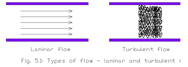
Laminar flow occurs in parallel layers, with no disruption between the layers. At low velocities the fluid tends to flow without lateral mixing, and adjacent layers move over one another. There are no cross currents perpendicular to the direction of flow. In laminar flow the motion of the particles of fluid is such that the particles are moving in straight lines parallel to the pipe walls.
In turbulent flow the fluid undergoes irregular fluctuations, or mixing. It is in contrast to laminar flow, in which the fluid moves in smooth paths or layers. In turbulent flow the velocity of the fluid at a point is continuously changing in both magnitude and direction. Common examples of turbulent flow are river flow, blood flow in arteries, oil transport in pipelines, ocean currents and flow through pumps and turbines.
5.6 Reynolds Number
The nature of the flow i.e. whether the flow is laminar or turbulent is determined by Reynolds Number, Re, given as:
![]()
Where ‘v’ is flow velocity, ‘d’ is pipe diameter, ‘ρ’ is the fluid density and ‘\[\eta \]’ is the fluid viscosity. For a given liquid flowing in a pipe the fluid density, fluid viscosity and the pipe diameter are constant. Thus, the value of Reynolds Number depends upon flow velocity.
Reynolds Number is a ratio and hence dimensionless. For a fully developed flow in a pipe flow is laminar for Re < 2000 and flow is turbulent for Re > 4000.
5.7 Bernoulli’s Principle
Recall that the total energy ‘E’ of a liquid flowing in a pipe is given by
E = Kinetic Energy + Potential Energy + Pressure Energy
And Kinetic Energy, \[K.E.\; = \;\frac{1}{2}m{v^2}\]
Potential Energy, PE = mgh
Pressure Energy = PV
Where ‘m’ is the mass, ‘v’ is the velocity, ‘h’ is the height, ‘P’ is the pressure and ‘V’ is the volume of liquid.
KE, PE and pressure energy when expressed as per unit weight of liquid are written as
\[\;\frac{{{v^2}}}{{2g}}\] , h and \[\frac{P}{{\rho g}}\] respectively.
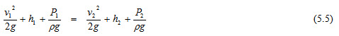
According to Bernoulli’s principle, the total energy of a liquid is constant neglecting any losses
\[E = \;\frac{{{v^2}}}{{2g}}\; + \;h\; + \;\frac{P}{{\rho g}}\quad=\] = constant (5.4)
Therefore, total energy of a flowing liquid at point 1 will be equal to total energy at point 2, i.e.
mgz1 + ½ mV12 + p1v1 = mgz2 + ½ mV22 + p2v2 (5.6)
where,
m = mass
g = acceleration due to gravity
z1 = head at 1
V1 = velocity at 1
v1 = volume at 1
p1 = pressure at 1
z2 = head at 2
V2 = velocity at 2
v2 = volume at 2
p2 = pressure at 2
Therefore, Bernoulli's principle states that for a fluid flow, an increase in the speed of the fluid occurs simultaneously with a decrease in pressure or a decrease in the fluids potential energy. Bernoulli's principle can be applied to various types of fluid flow, and equation (5.4) is called Bernoulli's equation. Bernoulli’s equation is best applicable under the following assumptions:
-
Fluid is under steady state flow, hence flow rate at all the positions in the pipe is not changing.
-
Fluid is having streamline flow, hence flow at all the points is exhibiting streamline or laminar flow.
-
Fluid is assumed to be of negligible viscosity, hence the fluid does not have tendency to stick on to the pipe.
Last modified: Friday, 14 March 2014, 12:12 PM