Site pages
Current course
Participants
General
Module 1. Hydraulic Basics
Module 2. Hydraulic Systems
MODULE 3.
MODULE 4.
MODULE 5.
MODULE 6.
MODULE 7.
MODULE 8.
LESSON 9. Reservoirs
9.1 Introduction
A hydraulic system usually consists of basic components like reservoir, pump, valves strainers, lines, etc. The hydraulic reservoir is a sort of fluid store house for the hydraulic system. It is having enough fluid to supply the normal operating requirements of the hydraulic system and an additional supply to replace fluid lost through minor leakages, if any. It also allows the settling of impurities like dust or dirt etc. The reservoirs may also be designed to do the separation of air from the fluid stored in it.
9.2 Reservoirs
A reservoir stores a liquid for transmitting the fluid energy. Hydraulic systems are generally operated by a liquid fluid being transmitted in the system components. The purpose of the hydraulic reservoir is to hold a volume of fluid, transfer heat from the system, allow solid contaminants to settle and facilitate the release of air and moisture from the fluid. A typical reservoir is shown in Fig. 9.1.
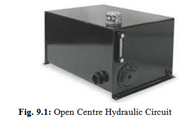
(Courtesy: http://www.htetechnologies.com/vendors/view/Lube%20Devicesl)
Hydraulic systems, on the other hand, need a very large quantity of liquid fluid which is to be stored and reused continually as the circuit works. Therefore, part of any hydraulic circuit is a storage reservoir or tank. This tank may be part of the machine framework or a separate unit. In general reservoir design and its development is very important. The efficiency of a hydraulic circuit is greatly affected by tank design. Hence a hydraulic reservoir does much more than just provides a place to store fluid. A well-designed reservoir does the following functions.
It should remove the gases if any.
It should dissipate the heat. It should allow time for contamination to settle down at the surface.
It should allow air bubbles to come to the surface and dissipate trapped air.
It should give a positive pressure to the pump inlet.
It may provide a convenient mounting place for the pump and motor, and valves.
There are different types of reservoirs which may be installed in hydraulic circuit and are discussed as under.
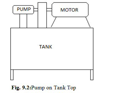
9.2.1 Pump on Tank Top
It is the most commonly used layout of reservoir and pump. The flat top surface of a reservoir makes a perfect place to mount the pump and motor as shown in Fig. 9.2. Axial or in-line piston pump life may be affected by vacuum at its inlet when using this layout. The piping in this configuration is kept sealed. Also the piping should have least number of bends and it should be as short as possible.
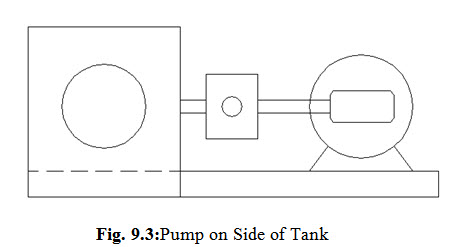
9.2.2 Pump at side of tank
It is another type of design which is used satisfactorily for any type of pump. This arrangement is sometime called a flooded suction, because the pump inlet always is filled with fluid. Still, there may be some vacuum in the inlet line when the pump is running. This design is considered to be better than the pump on top arrangement. Pump on side of tank layout is shown in Fig. 9.3.
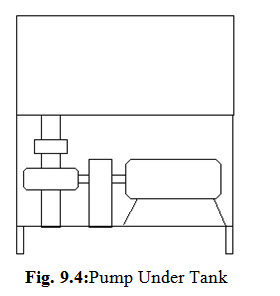
9.2.3 Pump under tank
It is one of the most useful pump and tank layout. In this design pump is kept below the reservoir to take advantage of static head pressure. Since the tank is above the pump, therefore the fluid is available at its inlet all the time. Pump under tank layout is shown in Fig. 9.4.
9.3 Shape of Reservoir
Shape of the reservoir should be such that it should have oil level as high as possible. For this high and narrow reservoirs are made rather than shallow and broad, which keeps the oil level high above the pump suction line. This prevents the vacuum at the line opening and thus prevents air from entering into the system. Aerated oil will not properly transmit power because air is compressible.
9.4 Size of Reservoir
While designing a reservoir the size is normally kept large enough so that it should have a reserve of oil with all the cylinders in a system fully extended. An oil reserve must be high enough to prevent a vortex (a whirling mass of fluid, especially one in which a force of suction operates, as a whirlpool) at the suction line opening. A reservoir must have sufficient space to hold all the oil when the cylinders are retracted, as well as allow space for expansion when the oil is hot. The size of reservoir in moving type of machine is generally kept in the range of 70 litre to 120 litre in a system requiring 350 LPM(Litre Per Minute) of oil flow rate. Whereas, for stationary equipment as a thumb rule, the size of reservoir is kept two to three times the pump output per minute. A large size tank is preferred for better cooling.
9.5 Location of Reservoir
In moving equipment reservoirs are normally located above the pumps, which create a flooded-pump-inlet condition. This condition reduces the possibility of pump cavitations (a condition where vapours are formed in low pressure region and when these vapours collapse on moving to high pressure region causing shocks and sometimes even erosion of metal parts).The location of a reservoir affects heat dissipation. Therefore while orienting the location of tank it should be kept in mind that tank walls should be exposed to the outside air.
9.6 Ventilation and Pressurization
Reservoirs are provided with vents to the atmosphere. A vent opening allows air to leave or enter the space above the oil as the level of the oil goes up or down. This maintains a constant atmospheric pressure above the surface of oil. A reservoir filter cap, with a filter element, is often used as a vent.
Last modified: Saturday, 15 March 2014, 5:46 AM