Site pages
Current course
Participants
General
Module 1. Hydraulic Basics
Module 2. Hydraulic Systems
MODULE 3.
MODULE 4.
MODULE 5.
MODULE 6.
MODULE 7.
MODULE 8.
LESSON 6. HYDRAULIC SYSTEMS
6.1 INTRODUCTION
Hydraulic systems are normally based on Pascal’s law in which a liquid is moved in a closed system in such a way that it uses the laws governing liquids to transmit power and do work. This lesson describes some basic types of hydraulic circuits and the major components used there in. A sump or a tank is utilized for the purpose of oil storage. Filters,strainers and magnetic plugs condition the fluid by removing harmful impurities that could clog passages and damage parts. Accumulators are used to store energy. Heat exchangers or coolers are generally provided to keep the oil temperature within safe limits as this helps in maintaining the oil properties.
6.2 Features of Hydraulic Systems
Hydraulic systems offer many advantages and some disadvantages as compared with other methods of power transmission. Some of the major advantages are:
- A hydraulic system is simple in design. In general a few standard hydraulic components replaces complicated mechanical linkages used in mechanical systems.
- The hydraulic systems are smooth and quiet in operation.
- The hydraulic components are connected with flexible pipes and hoses and therefore locating components in a setup is easier as compared to rigid mechanical elements.
- In hydraulic systems, a wide range of speed and forces can be controlled easily.
- It gives better efficiency with low friction loss which gives lower cost of power transmission.
A hydraulic system also has following disadvantages:
- Oil leakage is a fire hazard and is unsightly.
- Maintaining of the hydraulic system is costlier.
Care must be taken against rust, corrosion, dirt, oil deterioration etc.
6.3 Hydraulic Circuits
For the hydraulic fluid to do work, it must flow to the actuator, then return to a reservoir. The fluid is then filtered and re-pumped. The path taken by hydraulic fluid is called a hydraulic circuit of which there are several types. In this lesson two types of hydraulic circuits – closed centre type and open centre circuits are discussed. Closed centre circuits supply full pressure to the control valves, whether any valves are actuated or not. The pumps vary their flow rate, pumping very little hydraulic fluid until the operator actuates a valve. Open center circuits use pumps which supply a continuous flow.The flow is returned to tank through the control valve's open centre i.e. when the control valve is centred, it provides an open return path to tank and the fluid is not pumped to a high pressure.
6.4 Basic Hydraulic Closed Centre Circuit
In closed centre system circuit, the pump generally rests when the fluid is not required to operate an actuator or another device in the hydraulic circuit. This means that when the control valve is in the neutral position i.e. at the centre, the flow of the oil from the pump is altogether stopped or reduced to a minimum. The valve's spool therefore doesn't need an open centre return path to tank. A closed centre hydraulic system provides oil flow on demand, which enables simultaneous operation of many loads connected to one pump. A basic closed centre hydraulic circuit is shown in the Fig. 6.1.
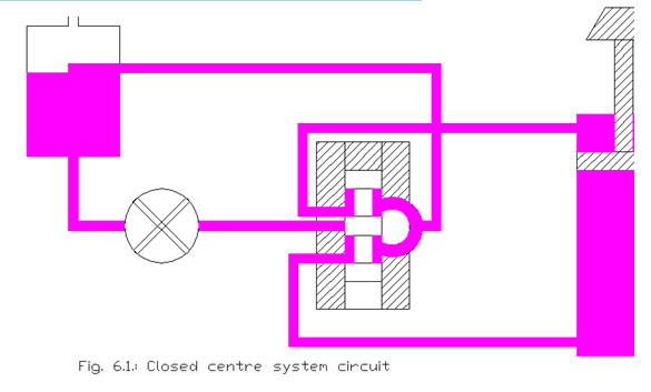
Closed centre hydraulic circuits almost always use variable flow pump. When a fixed displacement pump is used an accumulator is employed which is charged to required system pressure.
6.4.1 Fixed-Displacement Pump and Accumulator System
In fixed displacement pump and accumulator system, a pump of small but constant volume charges an accumulator. When the accumulator is charged to full pressure, an unloading valve diverts the pump flow back to a reservoir. A check valve traps the pressured oil in the circuit. On operating the control valve, an accumulator discharges its oil and actuation is caused into a cylinder. As pressure starts decreasing, an unloading valve directs the pump flow to an accumulator to recharge the flow. Since this system uses a small capacity pump, therefore, it is quite effective when operating oil is needed only for a short time. However, when there is a need of oil for longer periods, an accumulator system is not very effective unless provided with very large accumulator. A closed centre hydraulic circuit with fixed displacement pump and accumulator is shown in Fig. 6.2.

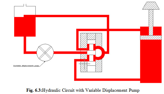
6.4.2 Variable Displacement Pump System
In this system, shown in Fig. 6.3,oil is pumped until the pressure rises to required system pressure when valve is at neutral position. A pressure-regulating valve allows the pump to stop and maintain this pressure to the valve. When the control valve is operating, oil is directed from the pump to the cylinder which raises the load. This causes the pressure to drop from maximum level and the pump is restarted. When the valve moves, the top of the piston connects to a return line and it allows the oil that was forced from the piston to return to the sump. When the valve is again positioned at neutral, the oil is trapped on both sides of the cylinder and the pressure in the passage between the pump and control valve begins to rise. When the pressure rises to required system pressure,the pump stops.
6.5 Advantages of Closed Centre Circuit
Relief valve is not required as the pump stops by itself when standby pressure is reached.
The size of the flow lines, valves, and cylinders etc can be chosen as per the flow requirements in the hydraulic circuit.
Closed centre system is more efficient as compared to open centre system as the pump does not function continuously.
Last modified: Saturday, 15 March 2014, 4:59 AM