Site pages
Current course
Participants
General
Module 1. Hydraulic Basics
Module 2. Hydraulic Systems
MODULE 3.
MODULE 4.
MODULE 5.
MODULE 6.
MODULE 7.
MODULE 8.
LESSON 8. Colour coding
8.1 Introduction
Hydraulics is the science of transmitting force or motion or both through the medium of confined fluid. Oil in a hydraulic system is in a state of rest or motion and the oil pressure is different in different sectors of the hydraulic circuit at any given time. The states of flow and pressure of the oil in a hydraulic system at a given time depends upon the stage of operation the system at that particular time. For example if a cylinder piston is extending towards the right, oil at high pressure is flowing from pump side into the left chamber of the cylinder and flowing out of the right chamber of the cylinder to the sump at low pressure. Similarly if a cylinder piston is fully extended towards right against a load, oil is at high pressure in the left chamber of the cylinder and oil flow is not taking place on both the sides of the piston. It is convenient to indicate the oilflow and pressure conditions in different parts of hydraulic circuits with industrial standardized colour codes.
8.2 Colour Coding
To understand or to depict the fluid states in hydraulic systems easily, Joint Industries Conference (JIC) and American National Standards Institute (ANSI) have established a standardized colour coding scheme for flow conditions or fluid paths as shown in Fig. 8.1.
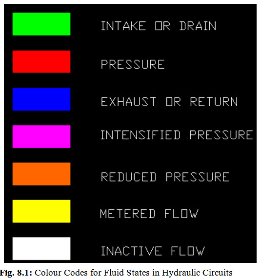
The significance of different colours is as follows:
Greencolour signifies the intake fluid which is piped from oil reservoir to pump in the hydraulic circuit.
The red colour generally signifies operating system pressure of the fluid. The oil from the pump flows through pressure relief valve to a directional control (DC) valve. The DC valve either blocks the flow or directs the flow to a cylinder. The resistance to fluid flow due to a closed DC valve or a cylinder piston causes pressure to be created. The fluid under pressure is shown in red colour.
The blue colour is used to indicate the fluid that is not restricted and having minimum oil pressure. It is generally used to show the oil exhausting from a cylinder or a valve to the sump.
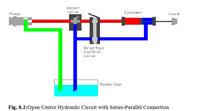
A hydraulic system in which the fluid conditions are indicated with green, red and blue colours is shown in Fig. 8.2.
-
Yellow indicates the controlled fluid flow or the oil which is metered through a restriction valve.
-
Orange is generally for the oil flow that has been reduced from the system pressure like the oil at the output of a pressure regulating valve.
-
Violet indicates the increased oil pressure due to the result of amplified system pressure, like oil with increased pressure at the output of intensifier
-
.White is used to indicate the oil pressure in a part of the system which has no pressure. For example, oil at the output of a cylinder having fully extended piston is shown in whitecolour as fluid from the rod end of the cylinder to the sump is inactive as there is no movement.
Last modified: Saturday, 15 March 2014, 5:25 AM