Site pages
Current course
Participants
General
Module 1. Hydraulic Basics
Module 2. Hydraulic Systems
MODULE 3.
MODULE 4.
MODULE 5.
MODULE 6.
MODULE 7.
MODULE 8.
LESSON 7. HYDRAULIC SYSTEMS
7.1 Introduction
Hydraulic circuits are of different types. Two major types of hydraulic circuits are closed centre circuit and open centre circuit. The two types were introduced and the closed centre hydraulic circuit was discussed in the previous lecture. The open centre hydraulic circuit is discussed in this chapter.
7.2 Basic Open Centre Hydraulic Circuit
Open center system uses a pump which provides constant flow of oil continuously. The flow is returned to sump through the open centre of control valve at neutral position. When the control valve is actuated the oil is routed to or from an actuator based on the control valve position. The pressure of oil will get increased to meet any resistance, since the pump has a constant output. If the pressure becomes too high, the oil returns to sump through a relieve valve.
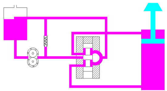
Fig. 7.1: Open Centre Hydraulic Circuit
An open centre hydraulic circuit is shown in Fig. 7.1. In this system, a control-valve (spool valve) is kept open at the center which allows the pump flow to pass through the valve and return to the sump. In order to operate several functions simultaneously, an open-center system must have the correct connections. An open-center system is normally efficient on single function but can also be utilized in multiple functions. Open center system may be in series, parallel or flow divider configuration.
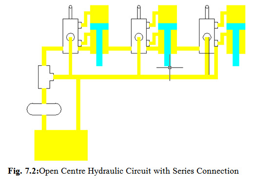
7.2.1 Series Connection
Opencenter systems with series connection have the oil from a pump applied to more than one open centre control valves fitted in series. A series connection with three functions is shown in Fig. 7.2. The return from the first valve is directed to the inlet of the second, and so on. When all the control valves are kept at neutral, the oil moves through the valves in series and returns to the sump. When a control valve is operated, the incoming oil is diverted to the cylinder that the valve serves. Return oil from the cylinder is moved through the return line and on to the next valve. This system is performing satisfactorily when only one valve is operating at a time. This ensures the full output of the pump at full system pressure for that particular function.
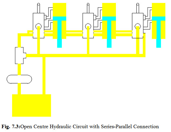
7.2.2 Series Parallel Connection
In this system oil from the pump is directed through the control valves in series as well as in parallel. When the valve is kept at neutral, the oil moves through the valves in series. On operating any one of the valve, the return is closed and the oil is available to all the valves through the parallel connection. Whereas, on operating two or more valves, the cylinder that needs the least pressure will operate first, then the cylinder with the next least pressure requirement, and so on so forth. Therefore, the series parallel connection has an advantage over the series connection when operating two or more valves simultaneously.
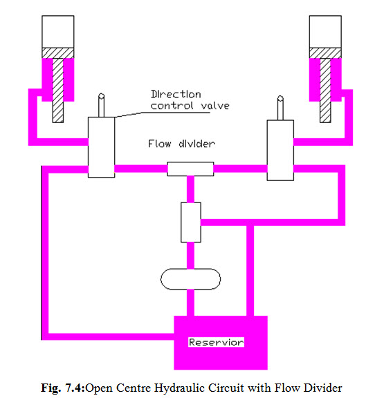
7.2.3 Flow Divider
A flow divider is a device which takes the volume of oil from a pump and divides it between two functions. An open Centre Hydraulic Circuit with Flow Divider is shown in Fig. 7.4. A flow divider used in open centre hydraulic circuit may be designed to open the left side first in case both control valves are actuated simultaneously. Or, it might divide the oil to both sides equally or in some other proportion. Hence the pump used in a flow divider circuit must be of larger capacity to operate all the functions in the hydraulic circuit simultaneously.
Last modified: Saturday, 15 March 2014, 5:19 AM