Site pages
Current course
Participants
General
Module 1. Perspective on Soil and Water Conservation
Module 2. Pre-requisites for Soil and Water Conse...
Module 3. Design of Permanent Gully Control Struct...
Module 4. Water Storage Structures
Module 5. Trenching and Diversion Structures
Module 6. Cost Estimation
Lesson 13. Design Requirements of Gully Control Structures
A structure installed across an active gully to stabilize the gully through control of erosion of gully bottom and banks is called gully control structure.
13.1 Design Requirements of Gully Control Structure
The gully control structures primarily designed for safe disposal of excess runoff generated from the watershed. While designing gully control structures three major points are considered, namely, (i) structure must have sufficient provision for safe discharge, (ii) the structure should have sufficient strength to withstand the pressure exerted by flowing water and (iii) the structure should be protected from erosion due to the flow passing over it. These points refer to hydrologic design, structural design and hydraulic design of structures. However, the design vigor depends on the type of gully control structures such as permanent structures require more vigorous design than temporary structures.
13.2 Functions or Purpose
The primary function of gully control structures is to provide safe passage to the flow through intervening into the prevailing slope of natural channel. The other purpose or function of gully control structures are listed below.
To reduce runoff erosive forces by stacking off the gradient of a gully and by controlling the course of flow to minimize ill effect on the banks.
To store water in the upstream as channel storage for irrigation.
To block sediment to keep it from damaging the downstream environment.
To maintain the stability of soil when vegetative cover is being established.
13.3 Causes of Failures
The structure failure caused mainly due to faulty hydrologic, hydraulic or structural design either alone or combination of these. However, there are cases when structures failed because of
· Insufficient capacity of structure
· Insufficient provision for dissipation of kinetic energy within the confine of structure
· Unprotected banks near to upstream of structures,
· Improper foundation causing uplift pressure to prevail over the body of the structure.
13.4 Types of Structures
Gully control structures can be grouped into two categories, namely, temporary gully control structures and permanent gully control structures. Temporary gully control structures are made up of locally available material and are designed for 3-10 years. Most of the check dams come under the category of temporary gully control structures. On the other hand, permanent gully control structures are designed for 25 to 50 years period.
13.4.1 Temporary Structures
All temporary structures should be practiced in G-1 type gullies. The purpose of this kind of dam is to temporarily maintain the stability of a gully and to make possible the establishment of vegetative cover. These are not durable and need frequent maintenance, though these are inexpensive and easy to build. These structures are constructed using the locally available material. The life of temporary structure is limited to 3-8 years.
Design Criteria of Temporary Structures
The overall height of a temporary check should not ordinarily be more than 75 cm. An effective height of about 30 cm is usually considered sufficient. Minimum 15 cm freeboard is necessary.
Life of the check dams under ordinary conditions should be 3-8 years and hence should be design for rainfall of 10 years return period.
Since the purpose of check dams in gully control is to eliminate grade in the channel, check dams theoretically should be spaced in such a way that the crest elevation of one will be same as the bottom elevation of the adjacent dam up-stream. Hence horizontal interval depends on the channel slope and height of check dam. Check dams of lesser height in higher slope will require more frequent check dams down the stream.
Suitable apron should be provided to avoid the souring due to the flow passing over these check dams. For this purpose, rip-rap is provided in the length of 1 to 1.5 meter downstream of the check dams. The gap between the rip-rap can be seeded with grass.
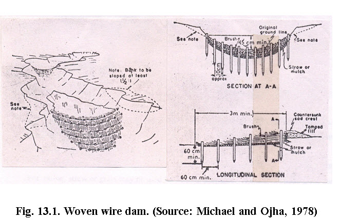
13.4.1.1 Woven Wire Dams
These dams are used in gullies of moderate slope and small drainage area. They help in the establishment of vegetation for permanent control of erosion. To construct a woven-wire dam a row of posts is set along the curve of the proposed dam at about 1.2 m intervals and 60-90 cm deep. Heavy gauge woven wire is placed against the post with the lower part set in a trench (15-20 cm deep) so that 25-30 cm projects above the ground surface along the spillway interval. Rock, brush or sod may be placed for approximately up to a length of 1.2 m to form the apron. For sealing the structure, straw, fine brush or similar material should be placed against the wire on the upstream side to the height of spillway crest. Fig.13.1 shows woven wire dam.
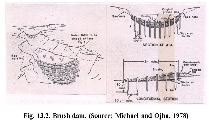
13.4.1.2 Brush Dams
They are cheap and easy to build, but least stable of all types of check dams. They are best suited for gullies with small drainage area. The center of the dam is kept lower than the ends to allow water to flow over the dam rather than around it. For a distance of 3-4.5 m along the site of structure, sides and bottom of the gully are covered with thin layer of straw or similar fine mulch. Brushes are then packed closely together over the mulch to about one half of the proposed height of dam. Several rows of stakes are then driven crosswise in the gully, with rows 60 cm apart, and stakes 30-60 cm apart in the rows. Heavy galvanized wire is used to fasten the stakes in a row, as well as to firmly compress the brushes in places. Sometimes large stones are also placed on top of brush to keep it compressed and in close contact with the bottom of the gully. The major weakness is the difficulty of preventing the leaks and constant attention is required to plug openings of appropriate size with straw as they develop. Fig.13. 2 shows brush dam.
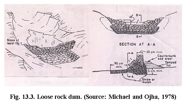
13.4.1.3 Loose Rock Dam
Loose rock dams are suitable for gullies have small to medium size drainage area. They are used in areas where stones or rocks of appreciable size and suitable quality are available. Flat stones are the best choice for dam making as they can be laid in such a way that the entire structure is keyed together. If round or irregular shed stones are used, structure is generally encased in woven-wire so as to prevent outside stones from being washed away. If the rocks are small, they should be enclosed in a cage of woven-wire. To construct the dam, a trench is first made across the gully to a depth of about 30 cm. This forms the base of the dam on which the stones are laid in rows and are brought to the required height. The center of the dam is kept lower than the sides to form spillway. To serve as an apron, several large flat rocks may be countersunk below the spillway, extending about 1 m down-stream from the base of the dam. Fig.13.3 shows loose rock dam.
13.5 Permanent Structures
Permanent structures are constructed when the benefits from such structures are justifiable compared to the cost of construction. General requirements of the permanent structures for gully control are: (1) they should be constructed with permanent materials, (2) they should have adequate capacity to handle the runoff, and (3) they should help in stabilizing the gully and store water wherever necessary. For the purpose of gully control, following types of structures are adopted.
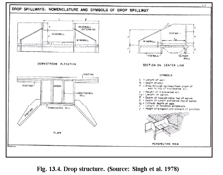
1) Drop structures: The drop structures are recommended for G-2 type of gully where the downstream fall of water is limited to 3.0 meter. The drop structures are used along the gully bed to act as control points so that the gully bed is not eroded below the crest level of the structure. Fig. 4 shows drop spillway.
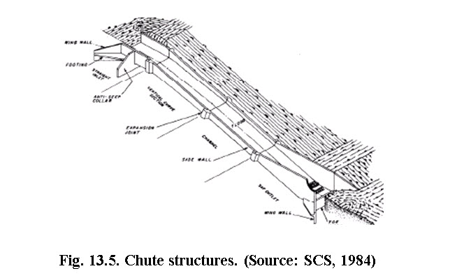
2) Chute structure: It is permanent type gully control structures in which the excess runoff are passed through chute spillway. This type of structure is recommended for G-3 type of gully where the gully depth is more than 3 meter. Fig. 5 shows chute spillway.
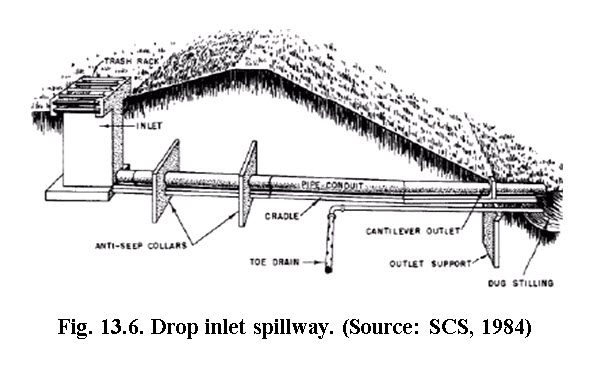
3) Drop inlet structures: These structures should be practiced in G-4 type of gullies where the depth is more than 9 meters and steep side slope exist. In this conditions the drop structures and chute structures are difficult to construct and practically not feasible. In this type of structures the runoff is guided through under lying pipe towards downstream. Fig. 6 shows drop inlet structure.
13.6 Planning for Gully Control
Control of gully erosion is done both by taking appropriate measures in the gully beds as well as in the catchment area. The first step in planning the gully control programme is to plan to control the runoff from the catchment area. This may be done by using good land and crop management practices, such as contouring, strip cropping and terracing. Gully control measures should be considered when the plan for the entire watershed is prepared.
Control of gullies may be an extensive operation and the cost of the gully control must be balanced by the benefits. Benefits include the protection of the adjoining areas, reduction of sediment load to the river system, storage of water and sometimes reclamation of the gully beds for cultivation purposes.
Reference:
Council of Agriculture, ROC Taiwan Provincial Soil and Water Conservation Burea' and the Chinese Soil and Water Conservation Society, ROC 1995, Soil Conservation Handbook, Food and Fertilizer Technology Centre, China.
Geyik, M. P. (1986). Watershed Management Field Manual - Gully Control. Food and Agriculture Organization of the United Nations, Rome.
Michael, A.M. and Ojha, T.P. (1978), Principles of Agricultural Engineering, Vol. II, Jain Brothers, New Delhi, India.
Murthy,V.V.N. (2008). Land and Water Management Engineering, Kalyani Publishers, pp. 333-359.
Singh, G. ,Venkataraman, C. and Shastry, G. (1981). Manual of Soil and Water Conservation Practices in India. Central Soil and Water Conservation Research and Training Institute, Dehradun
Soil Conservation Service, (1984). Engineering Field Manual. 4th Ed., USDA, Washington, D.C.
Suresh, R. (1997). Soil and Water Conservation Engineering, Second edition, Standard Publisher Distributors, Delhi, India.
Suggested readings
Soil Conservation Service, (1984). Engineering Field Manual. 4th Ed., USDA, Washington, D.C.
Suresh, R. (1997). Soil and Water Conservation Engineering, Second edition, Standard Publisher Distributors, Delhi, India.
Last modified: Wednesday, 5 February 2014, 6:32 AM