Site pages
Current course
Participants
General
Module 1. Perspective on Soil and Water Conservation
Module 2. Pre-requisites for Soil and Water Conse...
Module 3. Design of Permanent Gully Control Struct...
Module 4. Water Storage Structures
Module 5. Trenching and Diversion Structures
Module 6. Cost Estimation
Lesson 14. Design Procedure for Spillways
The gully control structures are essentially constructed across the well-defined natural channels. The temporary structures do not need meticulous and exhaustive design and is mostly constructed at G1 type gully. The height of the structure is generally less than 1m. These structures are low cost and made up of locally available material. The permanent structures are constructed at the places where temporary structures are not feasible. These structures are designed to carry heavy discharge and thus require exhaustive design. These structures are cost intensive and economy also figures as a major factor while designing these structures.
14.1 Components of Gully Control Structures
The gully control structures has three major components namely, inlet that allows the flow to enter the structure, embankment or main body that conveys the flow and outlet that safely dispose the flow.
14.1.1 Inlet
It is the part of structure through which water enters the structure. It may be either in the form of box or weir. The primary purpose of the inlet is to maintain the flow in steady state conditions so that its impact on the main structure could be minimized.
14.1.2 Main Body
It is that part, which, receives the flow from the inlet and leaves the same to the outlet through a conduit. The conduits can be either closed form (box type)or open form (rectangular channel).
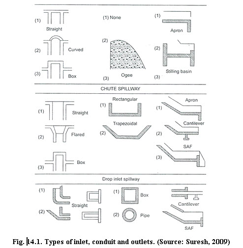
14.1.3 Outlet
It is downstream component of the structure, which discharges the flow into the gully with safe velocity. It dissipates the kinetic energy of falling discharge within the structure to prevent the downstream channel as well as structure from erosion. Different types of inlet, conduit and outlets are shown in Fig. 14.1.
The design feature of gully control structure requires a firm foundation. The foundation should be sufficient to hold the weight of the structures and strong enough the save the structure from overturning and buckling. Since these type of structures has to be remained in moist soil, adequate drainage system are required to avoid the phenomena of piping and uplift pressure that may cause structure unstable.
14.2 Selection Criteria of Gully Control Structures
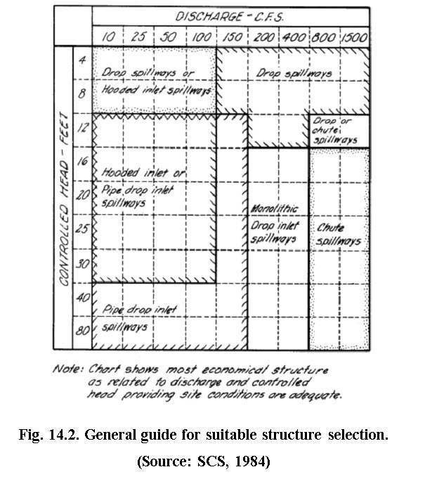
The different permanent gully control structures are similar in many respect expect the provision for conduit of the main body. These are divided into drop spillway, chute spillway and drop inlet spillway. The major criteria remain the height of fall for selecting the permanent gully control structures e.g. for less than 3 m fall, drop spillways are considered, for 3-6m fall, chute spillways and for more than 6m fall, drop in-let spillways are considered. For less than 1 m fall, temporary structures are recommended. Fig. 14.2 shows general guideline for selection of suitable structure (SCS, 1984).
14.3 Design Procedure (For Permanent Gully Control Structures)
The first step in the design procedure is being the on-site investigation and site selection. Site is finalized after conducting various surveys and investigations. These include topographic survey, sedimentation, land use, soil characteristics, socio-economic conditions and geologic investigation.
The channel profile survey using topographic maps is conducted for locating the suitable site after considering the native slope and uniform cross-section of the channel. This survey also indicates about the submergence area and storage volume upstream of the proposed structure. The sediment survey includes estimation of expected sedimentation rate. Land use survey includes worth of structure from the benefits (tangible and intangible) thus obtained. Socio-economic conditions refer to relative impact on the people in the vicinity of the proposed structures. The geologic investigation determines the suitability of the site for foundation and thus stability of the structure. The sites are selected after optimizing for all these conditions.
After site is selected, engineering design of the structures is carried out. This includes, hydrologic design that describes design inflow rate and amount, hydraulic design that includes determination of suitable dimension of various components of the structure and structural design that includes determination of specification and required strength of construction material considering desired safety.
14.3.1 Hydrologic Design
The hydrologic design includes estimation of peak flow that the structure is required to handle. This is essential in cased of drop and chute spillway, whereas the runoff volume information is required in case of drop inlet spillway. The design includes the probability analysis of rainfall for determining frequency or return period. The design return periods for different structures are presented in Table 14.1.
Table 14.1. Design frequency for various types of structures
|
Type of structure |
Frequency (years) |
|
Storage and diversion dams having permanent spillways |
50-100 |
|
Earth fill dam-storage having natural spillways |
25-50 |
|
Stock water dam |
25 |
|
Small permanent masonry gully control structure |
10-15 |
|
Terrace outlet and vegetated waterways |
10 |
|
Field diversion |
15 |
(Source: Samra et al. 2002)
Based on Table 14.1 the frequency for the particular structures isselected. Using the intensity-duration- frequency relationships (described in lesson 5)rainfall intensity is determined for selected location and peak runoff rate is estimated using the rational method.
14.3.2 Hydraulic Design
Hydraulic design consists of determining the dimensions of different components of the structure, on the basis of expected maximum runoff rate, that has been estimated in case of hydrologic design phase. The dimension of the structure should be sufficient to carry the design flow. Hydraulic design also deals with the study of the effect of flow on upstream and downstream reaches of the channel and dissipation of the kinetic energy of discharge falling towards downstream face of the structure. This phenomena helps in controlling the channel erosion below the structure. In this design standard principles of hydraulic and fluid mechanics are used which have been described in lessons 7 through 12. The hydraulic design example will be elaborated in lesson 16 for drop spillway.
14.3.3 Structural Design
Structural design involves the determination of strength and stability of different parts of the structure. It involves the analysis of various forces acting on the structure. They are mainly the water pressure which may be static or dynamic acting on the structure, forces developed due to overflow over the structure and the effect of water flow underneath the structure that is seepage and subsurface flow. The structure must be stable against these forces. In addition, the dimension of the structure should also be such that, the internal stress developed in the structure, must be resisted by the construction materials. The main objective for structural design is to determine the dimension of different components of the structures and material specification to withstand the various possible forces namely hydrostatic water pressure, self-weight of structure and up-lift pressure due to wet foundation. The design example is given in lesson 17 for drop spillway.
Reference
Council of Agriculture, ROC Taiwan Provincial Soil and Water Conservation Burea' and the Chinese Soil and Water Conservation Society, ROC 1995, Soil Conservation Handbook, Food and Fertilizer Technology Centre, China.
Geyik, M. P. (1986). FAO watershed management field manual - Gully control,
Food and Agriculture Organization of the United Nations, Rome.
Murthy,V.V.N.(2008). Land and Water Management Engineering, Kalyani
Publishers, pp. 333-359.
Samra, J.S., Sharda, V.N. and Sikka, A.K (2002). Water Harvesting and Recycling – Indian Experience, CSWCRTI, Dehradun. Pp 29-60.
SCS (1984). Engineering Field Manual. USDA, Washington, D. C.
Suresh,R. (2009). Soil and Water Conservation Engineering, Standard Publishers Distributors, Delhi, pp. 152-219.
Internet References
http://www.mfe.govt.nz/publications/land/soil-conservation-handbook-jun01/soil-conserv-handbook-jun01.pdf.
Suggested readings
Samra, J.S., Sharda, V.N. and Sikka, A.K (2002). Water Harvesting and Recycling – Indian Experience, CSWCRTI, Dehradun. Pp 29-60.
Suresh, R. (2009). Soil and Water Conservation Engineering, Standard Publishers Distributors, Delhi, pp. 152-219.
http://www.mfe.govt.nz/publications/land/soil-conservation-handbook-jun01/soil-conserv-handbook-jun01.pdf.
Last modified: Wednesday, 5 February 2014, 8:52 AM