Site pages
Current course
Participants
General
Module 1. Perspective on Soil and Water Conservation
Module 2. Pre-requisites for Soil and Water Conse...
Module 3. Design of Permanent Gully Control Struct...
Module 4. Water Storage Structures
Module 5. Trenching and Diversion Structures
Module 6. Cost Estimation
Lesson 15. Drop Spillway
The drop spillway is a weir structure. Flow passes through the weir opening, drops to an approximately level apron or stilling basin and then passes into the downstream channel. Drop spillway is one of the most commonly used gully control structures. It is mainly used at the gully bed to create a control point. Several such drop structures are constructed across the gully width throughout the length at fixed intervals. The series of such structures, develop a continuous break to flow of water, causing deposition of sediments and thus to filling the gully section. Sometimes, the drop structures are also used at the gully head to pass the flow safely and controlling the gully head. The different components of drop structures are shown Fig. 15.1.
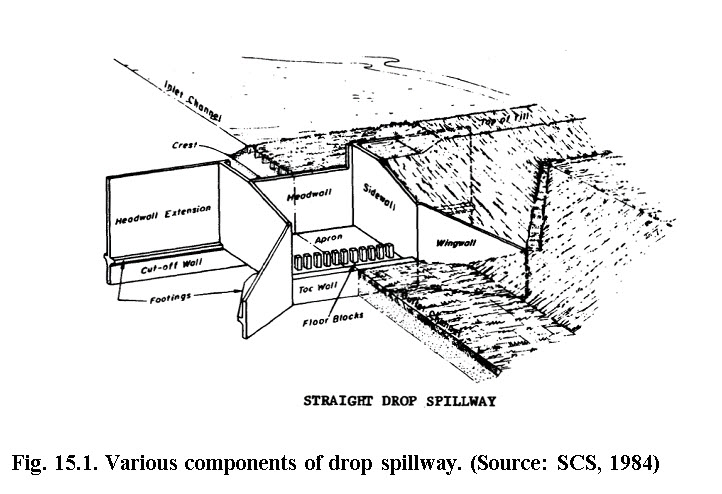
15.1 Different Components of Drop Structures
Head wall
Head wall extension
Side walls
Wing walls
Apron
Longitudinal sills
End sills
Cut-off walls
Toe wall
1. Head wall: It acts as a front wall against runoff in the drop spillway. It is constructed across the gully width. Headwall is provided with weir for passing through the flow.. Rectangular weir is most commonly used. The size of the weir should be sufficient to pass the design discharge safely.
2. Head wall extension: It is the extended portion of head wall into the gully sides. Its main function is to provide structural strength against sliding of the structure.
3. Sidewalls: These are constructed in the side along the gully walls. These two walls determine the apron section. The function of sidewalls is to prevent splashing of water over the gully banks and to confine the water flow within the apron.
4. Wing walls: These are constructed at the rear end of the structure, with some inclination, usually at 45° from the vertical. These walls are extended up to the gully sides and perform the function of preventing the flow backward into the space left between gully wall and side wall of the structure.
5. Apron: It is one of the main downstream components of the straight drop spillway. It receives the gully flow with high velocity and dissipates the kinetic energy of the flow to protect downstream channel from erosion.. It includes several blocks, which are elevated by some height and make the apron surface rough. This feature of apron is responsible for dissipating the maximum kinetic energy of falling water by creating hydraulic jump, as a result the velocity of outgoing water gets significantly reduced.
6. Longitudinal Sills: These are constructed in the apron section. They are constructed lengthwise parallel to the side walls. The sills are useful to make the apron, stable. Usually the sill height is 5-10 cm.
7. End Sills: End sills are the elevated portion of rear end of the apron. This is usually 10-30 cm height and make 45o angle to the apron surface. Its main function is to obstruct the water, going directly in to the channel, below.
8. Cut-off Walls: These are constructed to provide structural strength against sliding of the structure. They increase frictional resistance of the structure, which opposes the force causing to slide. In other words, cut-off walls acts as a key for the structure.
9. Toe Walls: These low walls are constructed at the bottom of the structure to prevent slippage or spreading of soil.
The inflow capacity of the straight drop structure is controlled by the size of the inlet i.e. notch, used. The notch is in form of a rectangular weir, in which flow is directly proportional to the length of the weir. The drop structure is used to control the velocity of runoff in a channel by lowering the water abruptly from one level to another.
15.2 Uses of Drop Structures
The various functional uses of this spillway are given as under:
Used for grade stabilization in lower reaches of waterways and outlets.
Used as an outlet structure in tile drainage system
Used for controlling the tail water at the outlet section of the conduit or spillway.
Used in the water distribution system for controlling irrigation.
Used as an outlet for disposing surface water from large areas, especially where drainage ditches exists.
Adaptability: The straight drop spillway is an efficient structure for controlling relatively low heads, normally up to 3m.
15.3 Material for Construction
Drop structures can be constructed with reinforced concrete, plain concrete, rock masonry, concrete blocks (with or without reinforcement)or sheet piling of steel, timber, and prefabricated metals.
Construction Requirement
-
Reinforced concrete is used in construction. The steel required for reinforcement is about 1-1.5% (based on experience of hilly watersheds) of the body weight of the structures.
-
The basin floor should be leveled transversely and longitudinally.
-
Upstream and or downstream channel transitions may be needed.
-
Concrete floor and wall thickness is usually 30-45 cm depending upon the flow velocity of the runoff and approach length available for inlet box. If approach length is more than 15 m, 30 cm thick wall can be recommended.
-
The depth of the concrete footing should not be less than 50 cm in any case for small- and medium- sized natural channel.
-
May need riprap or other form of erosion protection upstream and downstream of the drop structure where earthen channel exists.
-
The approach channel bed elevation should be same as the spillway crest elevation at the headwall.
15.4 Advantages
-
In this structure, the danger of undermining by rodents is not possible.
-
Straight drop spillways are less susceptible to get structural damaged, than the other structure.
-
As in other spillways (especially in drop-inlet) the conduit is likely to be clogged by debris, but in the drop spillway there is no such problem.
-
Its construction is very easy.
15.5 Disadvantages
There are some disadvantages of the drop spillways.
In the areas where discharge is less than 3 m3/s and total water head or drop exceeds 3 m, the construction of straight drop spillway proves to be costly affair, should not be preferred.
If the gully grade below the structure is not stable then it is impossible to construct a drop spillway.
The place where temporary storage is required to obtain a reduction in discharge, the construction of this structure is not technically justified.
References
SCS (1984). Engineering Field Manual. USDA, Washington, D. C.
Suresh, R. (1993). Soil and Water Conservation Engineering. New Delhi: Standard Publishers and Distributors.
Internet References
http://www.cecer.army.mil
Suggested Readings
Samra, J.S., Sharda, V.N. and Sikka, A.K. (2002). Water Harvesting and Recycling – Indian Experience, CSWCRTI, Dehradun. Pp 29-60
Sharda, V. N., Juyal, G.P., Prakash Chandra and Joshi, B.P. (2007). Training manual on Soil conservation and Watershed Management. Volume 2, Soil and water Conservation Engineering, CSWCRTI, Dehradun
Last modified: Wednesday, 5 February 2014, 8:58 AM