Site pages
Current course
Participants
General
Module 1. Perspective on Soil and Water Conservation
Module 2. Pre-requisites for Soil and Water Conse...
Module 3. Design of Permanent Gully Control Struct...
Module 4. Water Storage Structures
Module 5. Trenching and Diversion Structures
Module 6. Cost Estimation
Lesson 19. Drop Inlet Spillway
19.1 Components of Drop Inlet Structures
The drop inlet structures are the combination of 3 major components, namely, inlet, conduit and outlet. The structural design includes the determination of specification of these components. The usual function of a drop inlet spillway is to convey a portion of the runoff through or under an embankment without erosion.

19.1.1 Inlet
The inlet is installed having some drop which causes to flow of water from inlet to conduit. Various shapes of the inlet are used in the structures. Those include, box type, catch-pit and funnel shaped. The funnel shaped also known as morning glory or glory hole are widely used in the conditions where large amount of the flow to be handled. Design of inlet includes the determination of size and selection of shape in order to receive the excess flow and transfer it to conduit. The flow carrying capacity of the inlet and conduit and outlet must align adequately for proper functioning of the drop inlet structures. The size of the inlet largely depends on the amount of excess flow to be handled, however the shape depends upon the amount of excess flow as well as site conditions.
19.1.2 Conduit
The flow can be divided in two; first flow over weir in case of inlet and then it transforms to pipe or orifice flow in case of conduit. The flow in the conduit is governed largely by the slope of the conduit. This also influence the energy dissipated in term of head loss due to friction. The term natural slope is defined as the hydraulic slope for which the head loss due to friction is equated with the head gain due to elevation difference. These are given as
Head loss due to friction, 
In which Hf is head loss due to internal friction; L is length of the conduit, V is velocity of flow and Kc is head loss coefficient.
Natural slope (Sn) can be expressed as
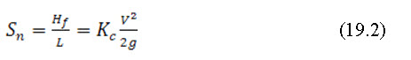
Slope of pipe can be taken as the sine of elevation and length of pipe. The friction factor for different pipe material is given in Table 19.1.
Table 19.1: Friction factor values of different pipe materials
|
Pipe materials |
Friction factor |
|
Aluminium |
0.34 |
|
Aluminium coated with steel |
0.25 |
|
Concrete |
0.03 |
|
Steel Pipe |
0.23 |
19.1.3 Outlet
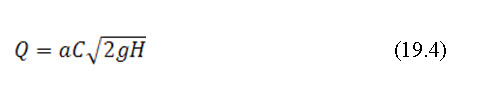
Different flow regimes at outlet can be expected depending upon the conditions of pipe slope and natural slope. For natural slope being greater than pipe slope and the inlet is submerged, the conduit will flow full and the capacity can be given as:

In which is the area of cross-section of conduit and is the coefficient of entrance loss at inlet.
For natural slope being less than the pipe slope and outlet is not submerged the flow is controlled by the inlet section of the conduit and can be given by standard orifice formula.
In which is the coefficient of discharge for the orifice.
19.2 Uses of Drop Inlet Spillways
A drop inlet spillway is normally used to drop low to medium volumes of water over a sharp incline (30%). The incline height is normally greater than 1 m with no upper limit. Common functional uses are given as:
Gully control
Surface water inlets to open ditches and terrace inlets
Principal spillways for farm ponds or reservoirs
Grade stabilization of gullies
Lower end of water disposal system
Principal spillways for debris basins
Used as culverts in roadway structures
Flood prevention structures
19.3 Adaptability
It is a very efficient structure for controlling relatively high gully heads, usually above 3 m. It is well adapted to sites providing an appreciable amount of temporary storage above the inlet. It may also be used for relatively low heads, as in the case of a drop inlet on a road culvert, or in passing surface water through a soil bank along a drainage ditch.
19.4 Advantages
For high heads, it requires less construction material than a drop spillway.
Where an appreciable amount of temporary storage is available, the capacity of the spillway can be materially reduced.
Reduction in construction cost.
A favorable factor in downstream channel grade stabilization and flood prevention.
19.5 Limitations
Small drop inlets are subject to stoppage by debris. It is limited to locations where satisfactory earth embankments can be constructed. Other disadvantages are as given below:
The entry point of the spillway normally concentrates the water-flow to a small area. This point can often plug with debris or local scouring can occur due to the high velocity of the water.
A proper design is required to prevent water from channeling along the sides of the pipe.
A head (or stage) of water is normally required to obtain full capacity of the inlet (this may make the berm height unreasonably high).
Spillway systems can be more expensive than comparable system for high flow rates.
19.6 Types of Drop Inlet Spillway
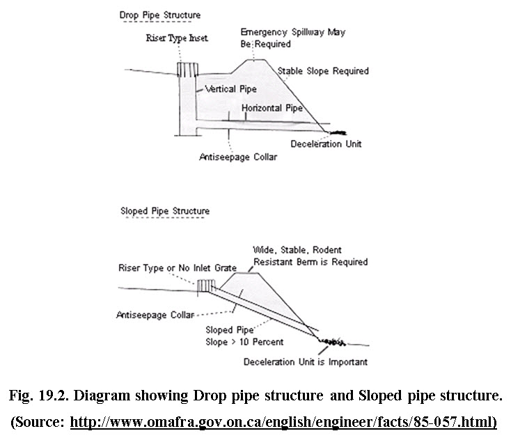
19.6.1 Drop Pipe Structure
This structure consists of two components, a vertical pipe and a horizontal pipe. The drop pipe can be square or round in cross-section which can be constructed of concrete, steel or plastic. The limiting flow factors are the flow over the crest of the vertical pipe and the capacity of the horizontal pipe. The flow over the crest is dependent on the circumference of the vertical pipe and the stage of water over it. The inlet should be as non-restrictive as possible since any obstructions will adversely affect the flow rate. The horizontal pipe is installed into the bottom side of the vertical pipe. The flow through this pipe is dependent on the head from the vertical pipe and the length and roughness of the pipe material. The horizontal pipe is normally smaller in diameter than the vertical pipe since the water running through it is under a higher pressure due to the increased head.
19.6.2 Sloped Pipe Structure
This structure consists of one component, a sloped pipe. Capacity is normally determined by the length and internal roughness of the pipe. Slope of the pipe has very little effect since under most circumstances the "critical slope" (slope at which flow capacity does not increase with increase of slope) is exceeded. Since the water is not forced into the pipe under a high head (as is the case with the horizontal pipe in a drop pipe structure) this structure has a much lower capacity.
19.7 Hydrologic Design
The Hydrologic design consists of knowing both the peak rate of runoff expected and also the inflow hydrograph. The hydrologic design procedure is similar as discussed in case of drop structures. The outflow will not be same as the inflow like other structures.
19.8 Hydraulic Design
It involves the design of earth dam and pipe spillway, as these two components are the main in drop inlet spillway.
19.8.1 Design of Earthen dam
The design of earth dam is also performed by considered all the designs steps – hydrologic, hydraulic and structural design, as in other hydraulic structures. The design of earthen dam suitable to drop inlet spillway is described as follows:
The upstream and downstream side slopes commonly used in earth dam are 3:1 and 2:1, respectively.
Top width of dam varies with its height. The minimum top width should be equal to 1.8m for the height of 3.5m. When top width of dam is used as a road, then it should be kept between 2.5 and 3.0m. In addition, there should also be added 30 cm additional top width for each 60 cm dam height.
In order to make the dam safe against overtopping, there must be added 5% of theoretical dam height or more to the dam height as a settling allowance and 60 cm as freeboard.
Bottom width of dam is calculated on the basis of side slopes and its height. The bottom width should match the length of conduit, used.
The side slopes of dam should be protected against erosion. This is performed by making rip- rap, using heavy gravels or rocks when upstream side slope is badly eroded by wave action. The downstream side slope is not affected by wave action, so vegetation can be grown to protect this side.
19.8.2 Design of Pipe Spillway
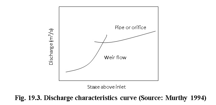
In drop inlet spillway, the pipe spillway has a vertical section towards upstream face of the dam, called riser, which is connected to the conduit passing through the dam. The top of the riser may be raised up to desired height, as per requirement for providing the grade to conduit and protecting the gully head. The flow capacity may be controlled by the inlet and conduit, both. To follow the hydraulic design of spillway, the types of flow occur in conduit should be considered. A typical discharge characteristic curve of drop inlet spillway is shown in Fig.19.3.
Example 19.1: Design Problem
Determine the size of concrete pipe needed in a drop inlet spillway for a peak flow of 3 cu. m per second and a total head of 3m. Determine the slope to be given to the pipe to flow full. Length of pipe = 12m, entrance loss coefficient Ke= 0.5 and friction loss coefficient Kc= 0.03
Solution:
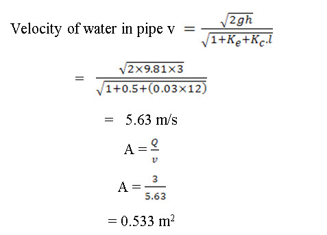
Therefore, dia. of pipe, d = 0.82 m; Select 85 cm dia. pipe
Neutral slope,
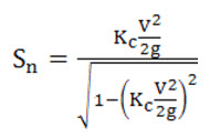 (Neglect second term in denominator)
Sn = 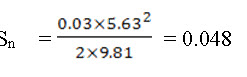
The downstream end of the pipe is kept 30 cm below the upstream end.
Actual slope, S= ![]() = 0.025; As S< Sn, the pipe will flow full.
= 0.025; As S< Sn, the pipe will flow full.
Design Problems
- A 50cm corrugated metal pipe of 75 m length is used in construction of drop inlet spillway. Given the head is 2m, entrance loss coefficient is 0.5. Estimate the peak discharge under pipe flow.
- Determine the diameter of a concrete pipe needed in a drop inlet spillway for a peak discharge of 12 m3/s if the actual slope of the pipe is 0.025.
Determine the size of concrete pipe needed in a drop inlet spillway for a peak flow of 5 m3/s and a total head of 2m. Determine the slope to be given to the pipe to flow full. Length of pipe = 20m.
References
-
Hilborn, D. (1985). Factsheet- Drop Inlet Spillway, Ontario Ministry of Agriculture, Food and Rural Affairs.
-
Murthy, V.V.N. (1994). Land and Water Management Engineering, Kalyani Publishers, New Delhi.
-
Suresh, N. (2009). Soil and Water Conservation Engineering, Standard Publishers, New Delhi.
Internet References
Suggested Readings
Murthy, V.V.N. (1994). Land and Water Management Engineering, Kalyani Publishers, New Delhi.
Suresh, N. (2009). Soil and Water Conservation Engineering, Standard Publishers, New Delhi.
Last modified: Tuesday, 11 February 2014, 5:51 AM