Site pages
Current course
Participants
General
Module 1. Perspective on Soil and Water Conservation
Module 2. Pre-requisites for Soil and Water Conse...
Module 3. Design of Permanent Gully Control Struct...
Module 4. Water Storage Structures
Module 5. Trenching and Diversion Structures
Module 6. Cost Estimation
Lesson 20. Drop Inlet Spillway Construction
In the previous lecture, general description about the drop inlet spillway along with its applicability, limitation and design considerations are discussed. The design issue for drop inlet structures includes design of inlet, earthen embankment and emergency spillway, selection and placement of pipe and provision to grip the pipe to minimize the piping effect within the body of embankment (anti-seep collars), and design on outlet. The design of a drop inlet spillway cannot be made independently of the design of the earth embankment, emergency spillway, and other elements of the total structure.
20.1 Constructional Features
20.1.1 Anti- Seep Collars
The anti-seep collars are primarily provided to check the adverse effect of piping phenomena by increasing the pipe length and cutting short the capillary gradient along a pipe conduit, which extends through an embankment. It also provide grip to the pipe for firm placement inside the embankment. The anti-seep collar can be of several types depending on the use and extent of piping potential. These are shown in Fig. 20.1.
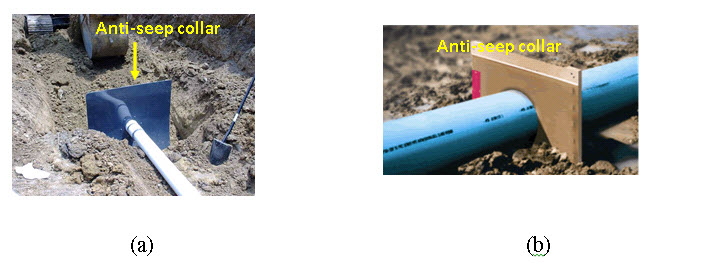
Fig. 20.1. (a) Anti-seep collar using single sheet metal. (b) Anti-seep collar using rubber/plastic sheet.
(Source:
and
The length of collar is kept about 30% of the total seepage length. The collars are constructed in the size of at least 2.5 m width and 2 m in height, centered around the conduit pipe. For concrete anti-seep collars, thickness should be 25 cm and these are reinforced with 1.2 cm dia steel rods at 30 cm interval. The number of collars to be required depends on the length of conduit used in the spillway.
20.1.2 Installation of Conduit
Generally, two types of conduits, namely, concrete pipe (drain pipe) and corrugated pipe (helical metal pipe) are used in drop inlet structure (Figure 20.2).
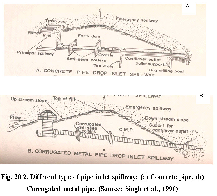
For smaller quantity of flow, helical metal pipe are used whereas for large quantity of flow, concrete pipes are used. In case of helical pipe usage, heavy pipe should be used and a coating of water repellent such as bitumen should be performed to increase the life of the pipe. The joints must be sealed to water tight using material such as rubber gasket fixed with Anti-seep collar to prevent the seepage along with the pipe as well as through the joints. The strength of the pipe and collar should be sufficient to bear the load of the embankment. If using cement concrete anti-seep collar, care must be taken for perfect alignment of the pipe because even little distortion will cause rupture of the collar. For ensuring uniform settlement along the pipe, attempt should be made to complete the installation of pipe in one go. When large size cement concrete pipe are planned, care should be taken to ensure that the concrete pipe has proper steel reinforcement and possess sufficient compressive strength to bear the load of the embankment and water flowing within it. The other care given below should be taken as well. Anti-seep collars, when used, should be installed around all conduits through earth fills according to the following criteria:
Enough collars should be placed to increase the seepage length along the conduit by a minimum of 15%. This percentage is based on the length of pipe in the saturation zone.
Maximum collar spacing should be 14 times the minimum projection above the pipe. The minimum collar spacing should be 5 times the minimum projection.
Anti-seep collars should be placed within the saturation zone. In cases where the spacing limit will not allow this, at least one collar should be in the saturation zone.
All anti-seep collars and their connections to the conduit should be watertight and made of material compatible with the conduit.
Collar dimensions should extend a minimum of 2 feet in all directions around the pipe.
Anti-seep collars should be placed a minimum of 2 feet from pipe joints unless flanged joints are used.
20.1.3 Cradle to the Conduit
To prevent uneven settlement and to develop hoop stress in the concrete pipes a cradle of masonry or concrete is provided to the conduit. Concrete pipes withstand more loads when hoop stress is developed than otherwise.
20.1.4 Earthen Embankment
Earthen embankment is briefly described in previous lecture and also separately discussed in later.
20.1.5 Emergency Spillway
If the runoff exceeds the design runoff, there is overtopping of the embankment and failure of the structure. To prevent such an occurrence, an emergency spillway is located on the embankment at the convenient location. It leads to downstream of the structure. The channel of the emergency spillway is protected with grass or stone pitching. The flood routing procedure gives the elevation at which the emergency spillway is to be located. Emergency earth spillways should have the capacity to discharge the peak flow from the watershed, resulting from a storm expected to occur once in 25 years, where the flow in the principal spillway is appreciable, the design capacity of the emergency spillway may be reduced by that amount.
20.1.6 Stone Pitching
It is recommended on the upstream side on the embankment and downstream side beyond the outlet to prevent soil erosion.
20.2 Maintenance
Any erosion control system needs regular attention to prevent any weak points and consequent failure. A checklist for spillways should be followed as below:
Obstructions in the inlet or the spillway should be removed. If these obstructions reoccur frequently a different inlet should be installed.
Watch for cracks in the berm or spillway foundation. If cracks occur, immediate repair will be required. Often the back slope will have to be decreased to prevent further failure.
Maintenance and inspection is especially important in the first couple of years after installation since the vegetation will not have developed fully and earth settlement may still be taking place.
Design Problem
The design discharge for drop inlet spillway are determined by the following relationship (Singh, et al. 1990):
Where,![]() is the volume of temporary storage (ha-m),
is the volume of temporary storage (ha-m),![]() is the volume of runoff (ha-m),
is the volume of runoff (ha-m),![]() is there quired principal spillway discharge (cumec) and,
is there quired principal spillway discharge (cumec) and, ![]() is thepeak flow from design storm (cumec).
is thepeak flow from design storm (cumec).
The above polynomial equation is solved for different ![]() and
and ![]() and the values are given in Table 20.1 for quick solution. For intermittent values of
and the values are given in Table 20.1 for quick solution. For intermittent values of![]() and,
and,![]() do the interpolation.
do the interpolation.
Table 20.1. Estimating principal spillway discharge allowing for temporary storage (for watershed of less than 100 ha)
|
|
|
|||||||||
|
|
0.00 |
0.01 |
0.02 |
0.03 |
0.04 |
0.05 |
0.06 |
0.07 |
0.08 |
0.09 |
|
0.0 |
1.00 |
0.99 |
0.98 |
0.96 |
0.95 |
0.94 |
0.92 |
0.91 |
0.90 |
0.88 |
|
0.1 |
0.87 |
0.85 |
0.84 |
0.82 |
0.81 |
0.79 |
0.78 |
0.76 |
0.74 |
0.73 |
|
0.2 |
0.72 |
0.70 |
0.68 |
0.67 |
0.65 |
0.64 |
0.62 |
0.61 |
0.60 |
0.58 |
|
0.3 |
0.57 |
0.55 |
0.54 |
052 |
0.51 |
0.50 |
0.49 |
0.47 |
0.46 |
0.45 |
|
0.4 |
0.44 |
0.43 |
0.42 |
0.41 |
0.40 |
0.39 |
0.38 |
0.37 |
0.36 |
0.35 |
|
0.5 |
0.34 |
0.33 |
0.32 |
0.31 |
0.30 |
0.29 |
0.28 |
0.27 |
0.27 |
026 |
|
0.6 |
0.25 |
0.24 |
0.23 |
0.23 |
0.22 |
0.21 |
0.20 |
0.20 |
0.19 |
0.18 |
|
0.7 |
0.18 |
0.17 |
0.16 |
0.15 |
0.15 |
0.14 |
0.14 |
0.13 |
0.12 |
0.12 |
|
0.8 |
0.11 |
0.11 |
0.10 |
0.09 |
0.09 |
0.08 |
0.08 |
0.07 |
0.07 |
0.06 |
|
0.9 |
0.05 |
0.05 |
0.04 |
0.04 |
0.04 |
0.03 |
0.02 |
0.02 |
0.01 |
0.01 |
(Source: Singh et al. 1990)
Fig. 20.3 along with Table 20.2a and 20.2b can be used to determine the capacity of 20 cm and 30 cm corrugated metal (CM) pipe drop inlets, as well as the height of riser required to provide the capacities for larger concrete pipes of 20 m length with correction factors for other lengths given in Table 10.3. The reinforced concrete pipes are used as drop inlet for embankment height of more than 6m. The concrete pipe must be cradled and bedded properly.
Size of riser pipe in relation to conduit pipe is determined as follows:
|
Inlet proportion |
|||||
|
Pipe conduit dia, D (cm) |
20-30 |
45 |
60 |
75 |
90 |
|
Pipe riser dia, D (cm) |
45 |
60 |
75 |
90 |
120 |
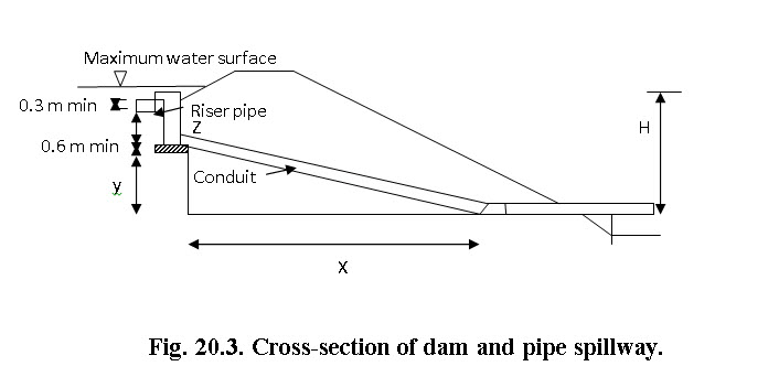
Determining height of riser: Using Table 20.2a and predetermined slope, find value of discharge for the selected conduit size. Compare this value of discharge with values given Table 20.2b.
(a) If Table 20.2 discharge value > table 20.2b discharge value (for the design head, conduit length and conduit size) riser height (z) should be minimum 5 times diameter of riser pipe (5D) to provide full pipe flow.
(b) If discharge is equal to or less than the table value of 20.2b, the riser height (z) should be less than 5D (minimum height = 0.6 m).
The outlet of the drop inlet spillway should be in line with the downstream channel. The layout providing the shortest conduit will exist when the conduit is straight and at a 90° angle with the centerline of the embankment.
For other diameter concrete drop inlet and conduit with 20 m length, the discharge capacity can be estimated using Table 20.3. For other length of conduit, the correction factors given in Table 20.3 are used to determine various dimension of pipe conduit.
Table 20.2a. Capacity for 20 and 30 cm dia pipes
|
Slope (%) |
Discharge (cumec) |
Slope (%) |
Discharge (cumec) |
||
|
|
20 cm pipe |
30 cm pipe |
|
20 cm pipe |
30 cm pipe |
|
5 |
0.04 |
0.116 |
18 |
0.076 |
0.221 |
|
6 |
0.042 |
0.127 |
19 |
0.076 |
0.227 |
|
7 |
0.048 |
0.139 |
20 |
0.079 |
0.232 |
|
8 |
0.051 |
0.147 |
21 |
0.082 |
0.238 |
|
9 |
0.054 |
0.156 |
22 |
0.082 |
0.244 |
|
10 |
0.057 |
0.164 |
23 |
0.085 |
0.249 |
|
11 |
0.059 |
0.173 |
24 |
0.088 |
0.255 |
|
12 |
0.062 |
0.181 |
25 |
0.088 |
0.26 |
|
13 |
0.065 |
0.187 |
26 |
0.091 |
0.263 |
|
14 |
0.068 |
0.19 |
27 |
0.093 |
0.269 |
|
15 |
0.068 |
0.201 |
28 |
0.093 |
0.275 |
|
16 |
0.071 |
0.207 |
29 |
0.096 |
0.28 |
|
17 |
0.074 |
0.215 |
30 |
0.096 |
0.286 |
Table 20.2b. Capacity (cumec) for pipe inlet
Head (H) |
20 cm conduit-45 cm riser for pipe length of |
30 cm conduit-45 cm riser for pipe length of |
|||||
|
Ft. |
m. |
50’ or 15.24m |
70’ or 21.34m |
90’ or 27.43m |
50’ or 15.24m |
70’ or 21.34m |
90’ or 27.43m |
|
5 |
1.52 |
0.051 |
0.045 |
0.04 |
0.14 |
0.12 |
0.11 |
|
6 |
1.83 |
0.057 |
0.048 |
0.042 |
0.16 |
0.14 |
0.12 |
|
7 |
2.13 |
0.059 |
0.054 |
0.048 |
0.17 |
0.15 |
0.13 |
|
8 |
2.44 |
0.065 |
0.057 |
0.051 |
0.18 |
0.16 |
0.14 |
|
9 |
2.74 |
0.068 |
0.059 |
0.054 |
0.19 |
0.17 |
0.15 |
|
10 |
3.05 |
0.074 |
0.062 |
0.057 |
0.2 |
0.18 |
0.16 |
|
11 |
3.35 |
0.076 |
0.065 |
0.059 |
0.21 |
0.19 |
0.17 |
|
12 |
3.66 |
0.079 |
0.068 |
0.062 |
0.22 |
0.2 |
0.18 |
|
13 |
3.96 |
0.082 |
0.071 |
0.065 |
0.23 |
0.2 |
0.18 |
|
14 |
4.27 |
0.085 |
0.074 |
0.065 |
0.24 |
0.21 |
0.19 |
|
15 |
4.57 |
0.088 |
0.076 |
0.068 |
0.25 |
0.22 |
0.2 |
|
16 |
4.88 |
0.091 |
0.077 |
0.071 |
0.25 |
0.22 |
0.2 |
|
17 |
5.18 |
0.093 |
0.082 |
0.072 |
0.26 |
0.23 |
0.21 |
|
18 |
5.49 |
0.096 |
0.085 |
0.076 |
0.27 |
0.24 |
0.22 |
|
19 |
5.79 |
0.099 |
0.088 |
0.076 |
0.28 |
0.25 |
0.22 |
|
20 |
6.1 |
0.102 |
0.088 |
0.079 |
0.29 |
0.25 |
0.23 |
Table 20.3. Discharge capacity Q, in cumec (Full pipe flow assumed) for R/C drop inlet, Ke + Kb = 0.65 with 20 m of R/C conduit; n = 0.013.
(Note: Multiply by correction factors for other pipe lengths)
|
Head dia.(m) |
30cm |
45cm |
60cm |
75cm |
90cm |
|
1.0 |
0.17 |
0.44 |
0.83 |
1.36 |
1.93 |
|
1.5 |
0.20 |
0.54 |
1.02 |
1.65 |
2.47 |
|
2.0 |
0.24 |
0.61 |
1.18 |
1.92 |
2.85 |
|
2.5 |
0.26 |
0.68 |
1.30 |
2.16 |
3.18 |
|
3.0 |
0.28 |
0.75 |
1.44 |
2.36 |
3.50 |
|
3.5 |
0.33 |
0.81 |
1.55 |
2.54 |
3.79 |
|
4.0 |
0.34 |
0.86 |
1.66 |
2.71 |
3.83 |
|
4.5 |
0.35 |
0.92 |
1.77 |
2.87 |
4.27 |
|
5.0 |
0.37 |
0.97 |
1.85 |
3.03 |
4.51 |
|
5.5 |
0.40 |
1.02 |
1.95 |
3.18 |
4.74 |
|
6.0 |
0.41 |
1.06 |
2.04 |
3.36 |
4.97 |
|
6.5 |
0.44 |
1.12 |
2.12 |
3.46 |
5.13 |
|
7.0 |
0.45 |
1.16 |
2.19 |
3.58 |
5.32 |
|
7.5 |
0.47 |
1.19 |
2.27 |
3.70 |
5.50 |
|
L(m) |
Correction factors for other pipe lengths |
||||
|
15 |
1.076 |
1.055 |
1.034 |
1.024 |
1.014 |
|
20 |
1.000 |
1.000 |
1.000 |
1.000 |
1.000 |
|
25 |
0.938 |
0.947 |
0.957 |
0.959 |
0.961 |
|
30 |
0.889 |
0.905 |
0.917 |
0.935 |
0.937 |
(Source: Singh et al 1990)
References
Singh, G., Venkataramanan, C., Sastry,G. and Joshi, B. P. (1990). Manual of Soil and Water Conservation Practices, Central Soil and Water Conservation Research and Training Institute, Dehradun.
SCS (1984). Engineering Field Manual Chapter 6- Structures, Soil Conservation Service, Page (6-33).
Murthy, V.V.N. (1994) Land and Water Management Engineering, Kalyani Publishers, New Delhi.
Suresh, R. (2009). Soil and Water Conservation Engineering, Standard Publishers, New Delhi.
Internet References
http://epubs.icar.org.in/ejournal/index.php/JAE/article/view/14419
http://www.iahr.org/membersonly/grazproceedings99/doc/000/000/159.htm
www.transportation.alberta.ca/Content/.../S13DsgnGdln.pdf
http://www.techtransfer.osmre.gov/nttmainsite/library/pub/ppdc/chapter6.pf
Suggested Readings
-
Singh, G., Venkataramanan, C., Sastry, G. and Joshi, B. P. (1990). Manual of Soil and Water Conservation Practices, Central Soil and Water Conservation Research and Training Institute, Dehradun.
-
SCS (1984). Engineering Field Manual Chapter 6- Structures, Soil Conservation Service, Page (6-33).
-
Murthy, V.V.N. (1994). Land and Water Management Engineering, Kalyani Publishers, New Delhi.
-
Suresh, R. (2009). Soil and Water Conservation Engineering, Standard Publishers, New Delhi.
Last modified: Tuesday, 11 February 2014, 6:48 AM