Site pages
Current course
Participants
General
Module 1. Perspective on Soil and Water Conservation
Module 2. Pre-requisites for Soil and Water Conse...
Module 3. Design of Permanent Gully Control Struct...
Module 4. Water Storage Structures
Module 5. Trenching and Diversion Structures
Module 6. Cost Estimation
Lesson 17. Structural Design of Drop Spillway-I
17.1 Structural Design
The structural design or stability of any hydraulic structure depends upon the interaction among the water, foundation soil and construction materials. Reinforcement, concrete, brick and masonry (stone) are most commonly used for construction. In addition to this, the dimensional proportion of different components of the structure other than those determined hydraulically, also affect the stability of the structure.
Failure of the head wall is the major problem for drop structure and this may occur due to the following reasons (Table 17.1):
Table 17.1. Factors responsible for different type of failure of hydraulic structure
|
Failure due to |
Factor responsible |
|
Overturning |
Inappropriate hydrologic design and substandard construction material |
|
Sliding |
Inappropriate structural design unable to sustain the fluid and earth pressure |
|
Tension |
Inappropriate reinforcement |
|
Compression |
Faulty reinforcement and concretes are not mixed homogenously causing differential settlement |
|
Piping |
Internal erosion due to poor construction material and inappropriate foundation. |
The structural design of the drop spillway involves thorough check for its stability to withstand above failures. Table 17.2 presents the function of different structural components from stability point view.
Table 17.2. Functions of components of drop spillway
|
Structural components |
Functions |
|
Head wall Extension |
Assist in creating stable fill |
|
Prevents piping under the structure |
|
|
Reduce uplift pressure |
|
|
Resist sliding of the structure |
|
|
Toe wall |
Prevents piping under structure |
|
Prevents undermining of the apron |
|
|
Side wall |
Helps in holding a stable fill |
|
Protects the fill against erosion from the flowing water, Passing over the spillway. |
|
|
Wing wall |
Helps in holding stable fill |
|
Protects the fill and gully banks against score by flowing Water. |
|
|
Head wall |
It is the main component of the drop spillway and is protected by the above components. |
(Source: Das, 2000)
17.2 Check against Overturning
The major factor behind overturning is the hydrostatic pressure caused by water column upstream of structure and active earth pressure due to filling. The structure should be checked for safety against overturning about toe of the structure. There are three scenarios that is to be tested for overturning, these include
Case 1: No earth fill against the head wall; i.e., only hydrostatic pressure exists. In this case the pressure of the water on the structure is maximum at the bottom and nil at the top and the pressure acts at the Centre of gravity of the pressure triangle.
Case 2: Soil filled up to the crest level; both hydrostatic and saturated soil pressure exists and the structure is only subjected to the saturated soil pressure.
Case 3: Soil filled up to the crest elevation and water is flowing over the crest. In this case the structure is subjected to the soil pressure, standing water pressure and pressure due to water flow above the crest.
For structural design of drop spillways, case 3 stands more appropriately.
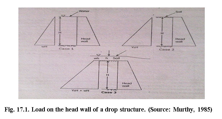
In cases 2 and 3 the pressure (Ps) due to soil fill over the headwall as presented by Murthy (1985) is as follows:
The forces Ps attempt to induce turning moment (T.M) to the structural components on which it is acting. The weight of different structural components produces retaining moment (R.M.) that counteracts the turning moment.
The factor of safely is given as ratio of restoring moment (R.M) to the turning moment (T.M) i.e.
If the value of factor of safety against overturning is more than 1.2 (for concrete) and 2.5 for masonry structure, then structure is assumed to be safe.
Restoring moment is the result of the weight of structure and turning moment is due to water and uplift pressure. The turning moment also depends upon the condition or nature of the sub soil strata. The uplift pressure is generally considered equal to the head of the water against headwall at u/s side) and zero at the downstream side. Its line of action is vertically upward from the centre of the structure. For safety point of view, the restoring moment should always be greater than the turning moment.
There may be site situation where the desired factor of safety of the structure is difficult to achieve but it is necessary to construct the structure. In this case, the anchoring is provided to balance the deficit moment between turning moment and restoring moment. In anchor design the deficit moment are balanced using tie rod (steel) which can sustain the pull due to this deficit moment.
17.3 Check against Sliding
The horizontal force acting on the structure in downstream direction may cause failure of structure by sliding. There are two types of forces resisting sliding; one is frictional resistance of the foundation and other is cohesion force of the soil and foundation, both. The sum of horizontal forces (∑H) should always be less than the resisting forces of the structure, for controlling the sliding action.
It is expressed as:
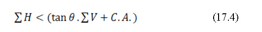
Where, f is the coefficient of friction (tan θ) of the soil; θ is the angle of repose or internal friction of the soil; ∑V is the total vertical force of the foundation material; A is the area of plane sliding.
To ensure the safety of structure against sliding, the value of sum of all resisting force must be equal to 1.5 times the sum of horizontal forces (i.e∑![]() Hf.). In case, if it is not satisfied, then the cutoff wall and toe of the wall should be constructed for greater depth. This yields more cohesive force. In addition to it, the base of the structure should also be made uneven, to increase the friction resistance of the structure.
Hf.). In case, if it is not satisfied, then the cutoff wall and toe of the wall should be constructed for greater depth. This yields more cohesive force. In addition to it, the base of the structure should also be made uneven, to increase the friction resistance of the structure.
Sliding of the structure may also be predicted by a factor, known as factor of safety against sliding. It is given as:

Where, F.Ss is the factor of safety against sliding;![]() is the sum of all horizontal forces which tend to slide the structure;is the sum of all vertical forces and is the uplift force.
is the sum of all horizontal forces which tend to slide the structure;is the sum of all vertical forces and is the uplift force.
The value of factor of safety against sliding should be greater than or equal to 0.8 for concrete and 0.75 for masonry.
17.4 Check against Piping
The piping type failure in hydraulic structure takes place due to removal of materials from the foundation by seepage water as it emerges from the soil below the structure. Removal soil material below the structure will ultimately leads to failure.
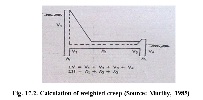
There are two basic thoughts about piping phenomenon, in which one related with the flow of water through the foundation materials and the other is related with the line of creep. The line of creep is the contact surface between the structure and soil at the base of the foundation as of least resistance to flow.
Several studies have reported that most of the structures are failed due to piping, mainly along the line of creep. The value of safe weighted creep ratio (Cw) of different soil types can be calculated, using the following formula and can be have an idea about the failure of structure due piping. The formula is given as:
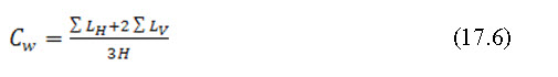
Where, Cw is the weighted creep ratio; ![]() is the sum of all horizontal or flat contact lengths;
is the sum of all horizontal or flat contact lengths; ![]() is the sum of all vertical or steep contact lengths and His the head between head and tail water depths.
is the sum of all vertical or steep contact lengths and His the head between head and tail water depths.
The recommended values of weighted creep ratio for different types of materials are given in Table 17.3. The computed values of Cw should always be either equal to or greater than the recommended values to have stable structure. If it does not satisfy, then depth of cutoff or toe wall should be suitably increased to obtain the desired Cw value.
Table 17.3. Values of weighted creep ratio for different substrata
|
Soil type |
Cw |
|
Clear gravel |
5.0 |
|
Clean sand or sand and gravel mixture |
6.5 |
|
Very Fine sand and silt |
8.5 |
|
Mixture of well graded sand silt and clay(less than 15%) |
5.5 |
|
Mixture of well graded sand silt and clay(More than 15%) |
4.0 |
|
Firm clay |
2.3 |
|
Hard clay |
1.8 |
(Source: USDA, 1957)
17.5 Check against Tension
In case of bricks or stone masonries structure, it should be ensured that tension should not be developed at the base of the head wall, as these materials are not capable to bear tensile stress. This is done by ensuring the resultant force acting on the head wall, passing through the middle third of the base of structure. The position of resultant forces may be calculated by using following equation.
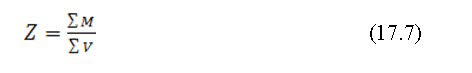
Where, Z is the position at which resultant forces is acting i.e. horizontal distance measured from the wall to the point of action of vertical force.is the sum of all the horizontal forces; is the sum of all vertical forces
The eccentricity (e) is given as:

It should not be greater than d/6 in which d is denoted as base length.
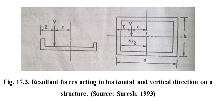
17.6 Check for Compression
It is performed by determining the resultant forces, acting on the structure. The resultant force is due to the load transmitted on the foundation of the structure, as the result of all horizontal and vertical forces acting on the structure. This is also called contact pressure. It is acting vertically downward i.e. compressive nature. This makes the structure stable against floating. The contact pressure may be calculated, using the following formula:
Where, P is the contact pressure; ![]() is the sum of all vertical forces including uplift forces; A is the base area of the structure; e is the eccentricity (i.e. longitudinal distance from the centroid of the base area to the point of application of the resultant vertical forces) and d is the base length of the structure.
is the sum of all vertical forces including uplift forces; A is the base area of the structure; e is the eccentricity (i.e. longitudinal distance from the centroid of the base area to the point of application of the resultant vertical forces) and d is the base length of the structure.
References
Das, G. (2000). Hydrology and Soil Conservation Engineering. EEE Publication. Prentice – Hall of India Pvt. Ltd. New Delhi.
Michael, A.M., and Ojha, T.P. (2006). Principles of Agricultural Engineering. Volume-II. Jain Brothers. New Delhi.
Murthy, V. V. N. (1985). Land and Water Management Engineering. Kalyani Publisher, New Delhi.
Suresh, R. (1993). Soil and Water Conservation Engineering. Standard Publishers and Distributors, New Delhi.
Internet References
http://www.georgiaplanning.com
http://jps.penang.gov.my
http://directives.sc.egov.usda.gov
http://conservancy.umn.edu
Suggested Readings
Das, G. (2000). Hydrology and Soil Conservation Engineering. EEE Publication. Prentice – Hall of India Pvt. Ltd. New Delhi.
Michael, A.M., and Ojha, T.P. (2006). Principles of Agricultural Engineering.Volume-II. Jain Brothers. New Delhi.
Suresh, R. (1993). Soil and Water Conservation Engineering. Standard Publishers and Distributors, New Delhi.
Last modified: Wednesday, 5 February 2014, 12:01 PM