Site pages
Current course
Participants
General
Module 1. Perspective on Soil and Water Conservation
Module 2. Pre-requisites for Soil and Water Conse...
Module 3. Design of Permanent Gully Control Struct...
Module 4. Water Storage Structures
Module 5. Trenching and Diversion Structures
Module 6. Cost Estimation
Lesson 18. Structural Design of Drop Spillway-II
In the previous lectures, concepts of hydrologic, hydraulic and structural design of drop spillway are discussed. In this lecture, structural design will be carried out considering the hydrologic and hydraulic designs carried out in example 16.1.
18.1 Design Example
Design the structure of a straight inlet drop spillway with a straight apron outlet, to be installed for gully control. The expected peak runoff rate through the gully is 5.83 m3/s. For dimension of the structure refer example 16.1. Assume fill condition for the design.
Soil
Angle of internal friction = 25o
Cohesion resistance = 500 Kg/m3
Unit weight of soil = 1900 Kg /m3
Brick
- Unit weight of masonry = 1900 Kg /m3
Foundation
- Made of firm clay. Its creep ratio, Cw = 2.3
Water
- Unit weight of water = 1000 Kg/m3
Solution:
From example 16.1
The crest length of weir, L = 4.0 m
and h = 0.97 m
Apron length, Lb= 3.25 m
Cutoff wall / toe wall = 0.567 m = 0.57 m
Total uplift pressure head = F = 2 m

Analysis of forces
|
Forces |
Volume of component (m3) |
Material Density (Kg/m3) |
Force/unit length of structure (Kg/m) |
Lever arm length (m) |
Moment kg |
Type of moment |
|
P1 |
2 x 0.97 x 1 |
1000 (water) |
1940 |
At 0.5 x 2 = 1.0 from base |
1940 |
overturning |
|
P2and P3 |
0.5 x 2 x 2 x 1 |
1000 (water), 1900 (soil) |
2000+3800 =5800 |
At 1/3 x 2 = 0.66 from base |
3862.8 |
Overturning |
|
Pu1 |
(0.5 x 1.43 x 4.75) x 1 |
1000 (water) |
3396.25 |
At 2/3 x 4.75 = 3.16 from toe |
10754.8 |
Overturning |
|
Pu2 |
0.57 x 4.75 x 1 |
1000 (water) |
2707.5 |
At 0.5 x 4.75 = 2.375 |
6430. 31 |
Overturning |
|
Total overturning moment |
22987.91 |
|||||
|
W1 |
2 x 1 x 1 |
2100 (Bick masonry) |
4200 |
At 4.75 – 0.5 4.25 from toe |
17850 |
Restoring |
|
W2 |
0.5 x 2 x 1 x 0.5 |
2100 (Brick masonry) |
1050 |
At 3.25 + (2/3) x 0.5 = 3.55 from toe |
3762.5 |
Restoring |
|
W3 |
4.75 x 0.57 x 1 |
2100 (Brick masonry) |
5685.75 |
At 0.5 x 4.75 = 2.375 from toe |
13503.65 |
Restoring |
|
Total restoring moment |
35116.15 |
|||||
Safety against Overturning: For safety against overturning,
Total restoring moment > Total overturning moment
i.e., 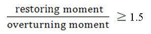
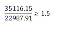
Therefore, the structure designed is safe against overturning.
Safety against Sliding: For safety against sliding, ΣH shouldn’t be greater than f.ΣV + CA, where horizontal forces, H= P1 +P2+ P3, Vertical forces, V = W1 +W2 + W3 – Pu1 –Pu2, and f = tan ѳ(angle of internal friction of soil), C is the cohesion resistance of soil, and A = area of the plane of sliding.
ΣH = 1940 + 5800 = 7740 kg/m
ΣV = 4200+1050+5685.75 – (3396.25+2707.5) = 4832 kg/m
fΣV + CA = 0.466 x 4832 + 500 x 4.75 x 2 =7001.712 kg/m
As this is greater than ΣH, the structure is safe against sliding.
Safety against Tension
Assuming restoring moments as positive and turning moments as negative, the value of z is calculated as:
z = ΣH/ΣV
= (35116.15- 22987.91) / 4832 = 2.50
e = 2.50 – (4.75/2) = 0.125 m
width (d)/6 = 4.75/6 = 0.791 m
This shows that, e = 0.125 is less than 0.791 and structure is therefore safe against tension.
Safety against Compression
For safety against compression, the forces should be compressive in nature, so that there is no floatation of the structure.
Contact pressure,
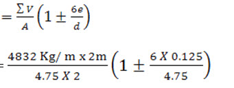
= 1017.26 +160.62 Kg / m2
= 1177.9 Kg / m2at upstream side
=856.64 Kg / m2at downstream side
Hence the resultant pressure is downward and, therefore the structure is safe against compression.
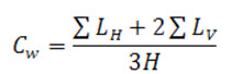
Safety against Piping
For safety against piping, the weighted creep ratio Cw should be higher than the recommended value.
Assume depth of cutoff walls on the upstream and downstream sides = 1 m
Here,
ΣLh= 4.75 m
2 ΣLv= 2 x (2 x 1.57 + 2 x 1) = 10.28 m
H = 2 m
Therefore, 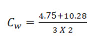 = 2.505
and for clay Cw = 2.3 which is less than 2.505 therefore, the structure is safe against piping. Hence the dimensions calculated are satisfactory.
References
Das, G. (2000). Hydrology and Soil Conservation Engineering. EEE Publication. Prentice – Hall of India Pvt. Ltd. New Delhi.
Michael, A.M., and Ojha, T.P. (2006). Principles of Agricultural Engineering. Volume-II. Jain Brothers. New Delhi.
Murthy, V. V. N. (1985). Land and Water Management Engineering. Kalyani Publisher, New Delhi.
Suresh, R. (1993). Soil and Water Conservation Engineering. Standard Publishers and Distributors, New Delhi.
Internet References
http://www.georgiaplanning.com
http://jps.penang.gov.my
http://directives.sc.egov.usda.gov
http://conservancy.umn.edu
Suggested Readings
Das, G. (2000). Hydrology and Soil Conservation Engineering. EEE Publication. Prentice – Hall of India Pvt. Ltd. New Delhi.
Michael, A.M., andOjha, T.P. (2006). Principles of Agricultural Engineering.Volume-II. Jain Brothers. New Delhi.
Suresh, R. (1993). Soil and Water Conservation Engineering. Standard Publishers and Distributors, New Delhi.
Last modified: Friday, 7 February 2014, 10:52 AM