Site pages
Current course
Participants
General
Module 1. Perspective on Soil and Water Conservation
Module 2. Pre-requisites for Soil and Water Conse...
Module 3. Design of Permanent Gully Control Struct...
Module 4. Water Storage Structures
Module 5. Trenching and Diversion Structures
Module 6. Cost Estimation
Lesson 21. Chute Spillway
21.1 Chute Spillway and Its Uses
Chute spillway is an open channel like structure, which is constructed on steep slope of the gully face with a suitable inlet and outlet. It usually consists of an inlet, vertical curve section, steep-sloped channel and outlet. The major part of the drop in water surface takes place in a channel. Flow passes through the inlet and down the paved channel to the floor of the outlet. It handles the flow having supercritical velocity.
The chute, specially the concrete chute is adapted to high overfall, where a full flow structure is required and where site conditions do not permit the use of a detention type structure. It may also be used with detention dams, taking advantage of the temporary storage to reduce the required capacity and the cost of the chute. It is usually more economical than a drop-inlet structure, when large capacities are required. For high drop (3 to 6 m) and discharge capacity, chute spillways are cheaper than drop spillways as they require less construction material. A typical chute spillway is shown in Fig. 21.1.
Chute spillway is generally used
(i) to control gully head;
(ii) to convey the runoff from upstream areas into the gully, very smoothly without erosion;
(iii) as a structure for flood prevention, water conservation and collection of sediments and
(iv) for controlling the gradient of natural or artificial channels.
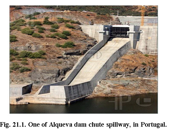
(Source:http://www.featurepics.com/online/Chute-Spillway-1624769.aspx)
21.2 Adaptability
The chute spillways are suitable for following conditions:
(i) For high overfalls, where a full flow structure is required.
(ii) Where site conditions are not suitable for constructing drop spillway.
(iii) This spillway can also be constructed in combination of check dams and other detention type structures.
21.3 Limitations
The various limitations of chute spillway are as under:
(i) There is considerable danger of undermining due to rodents. For which, additional precautions are required.
(ii) In poorly drained areas, there is problem of seepage. Such areas are not suitable for chute spillways as seepage tends to weaken the foundation. In such areas if constructing of chute spillway is very essential and no other substitutes are available, then provisions to control the seepage problem are essentially made.
(iii) From safety point of view, the construction site should be compacted very well or when earth filling is done that should also be compacted thoroughly. It is an additional work, which takes time and money both.
21.4 Components of Chute Spillway
The various components of standard chute spillways are shown in Fig. 21.2.
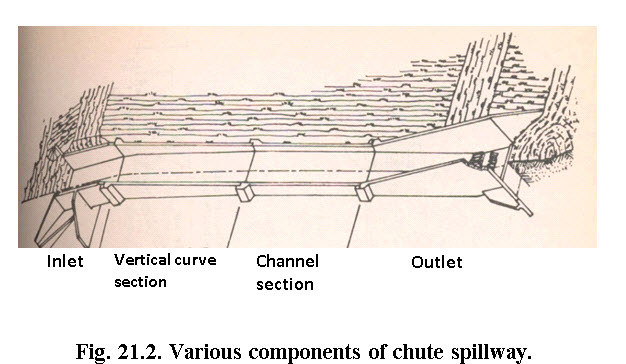
(Source: Singh et al., 1990)
21.4.1 Inlet
The following three types of inlets are used with chute spillways:
(i) Straight inlet
(ii) Flared or side channel inlet
(iii) Box (rectangular) type inlet
The box type inlet is generally used when straight type inlet is not sufficient to handle the runoff at desire drop. The inlet section governs discharge capacity of structure. Vertical walls extending into the soil foundations under the inlet are known as cutoff walls. Their main purpose is to prevent water seepage under the structure. Similar walls, extending laterally from the inlet to prevent seepage and erosion around the ends of the structure, are called headwall extensions. These walls also protect against burrowing animals.
The hydraulic design of inlet involves the design of weir length. It is determined by using the weir formula:
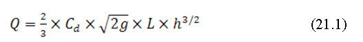
Where, Q is the peak discharge rate, m3/s; Cd is the coefficient of discharge = 0.6;Lis the weir length, m and h is the head of flow, m.
21.4.2 Conduit or Chute Discharge Carrier
The conduit is the part of chute spillway which convey water from inlet to the outlet section. It can be rectangular or a trapezoidal channel. Usually the conduit section is adopted considering the dimensions of the inlet section. Sometimes, more or less same section as that of inlet is used for the conduit also. The side walls of conduit confine the flow rate and discharge distribution, too, within the conduit section. The top wall of conduit is constructed in such a way, that it may be flushed with the embankment slope. Manning’s formula is used for the design of channel capacity. Design of channel cross-section is similar to the design of open channel, in which bottom width, top width, side slope and depth are determined for a given discharge rate.
21.4.3 Outlet
Outlet section of chute spillway is located at the downstream end. It is also called as energy dissipater because, it dissipates the energy of falling water from higher to lower elevation By decreasing the velocity of flow. Thus it protects downstream area from the soil erosion. At the outlet section, energy dissipates on the concept of hydraulic jump. This hydraulic jump is the formed on the horizontal part of the basin. The Froud number (F) of incoming flow into the outlet and corresponding downstream water depth (d2) should satisfy the following equation.
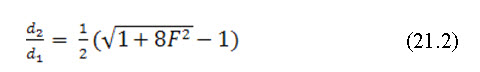
Where, V1 is the sequent depth ratio that means ratio of depth of flow after hydraulic jump and before hydraulic jump.
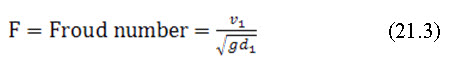
Here,V1 is the flow velocity before occurrence of hydraulic jump and g is acceleration due to gravity.
Chute spillway outlet may include Chute blocks, baffle blocks, stilling basin, end sill and side (training) walls. It is preferable to keep them vertical on water side for the satisfactory formation of hydraulic jump. When the velocity at entry of stilling basin is high, chute and baffle blocks are omitted. The outlet's capacity is verified by different considerations of critical depth of flow. Straight apron can also be used for small structures. Scour at the outlet is one of the important factors leading to failure of structure. Scour may be controlled by giving proper consideration in the design to the:
Stability of the grade below the structure.
Velocities occurring in the downstream channel.
Tail water elevations for different flow stages.
Dissipation of water energy in the outlet.
Scour below drop spillways or chutes usually are reduced as the tail water elevation is increased.
21.5 Hydrologic Design
The peak flood for which the chute spillway is to be designed will govern the size and capacity. It involves the estimation of run-off rate and flood volume depends on several factors associated with the runoff. The design peak runoff volume using Rational method are computed for the design rainfall intensity of 25-30 years return period.
21.6 Hydraulic Design of Components
Hydraulic design involves determining the dimension of different components of structure, on the basis of expected maximum runoff rate, that has been estimated in hydrologic design phase. The dimension of structure should be able to handle design runoff. The detailed structural design of chute spillway will be discussed in lesson 22.
Hydraulic design of inlet and conduit is already discussed earlier. Chute spillways are used for different purposes.. These could be as large as spillways for huge dam of river valley projects, or small size structure for gully control and conveyance of water from canals. For gully control as per the recommendation of USDA (Agr. Handbook, 135), the following four types of outlets are generally used.
1. Straight Apron
2. Cantilever
3. SAF (Saint Anthony Falls)
4. Baffle
A straight apron type of outlet is simplest of all, and its design is same as drop spillways. The cantilever type is used where channel grade and soil below the structure are unstable. The SAF (Saint Anthony Falls) stilling basins, developed at Saint Anthony Falls hydraulics laboratory (USA) is the most common of all stilling basins widely used in several applications of chute spillways. The design of SAF will be discussed in next chapter.
Example 21.1:
The chute spillway is to be provided with a straight inlet with peak flow discharge 3.57 m3/s. The depth of flow is to have 1.28 m. What should be the weir length? (Cd = 0.6)
Solution:
Given:
Head = 1.28 m
Q = 3.57m3/s
Cd = 0.6
The discharge over the weir is given by the equation as
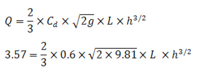
L= 1.39 m Ans.
Example 21.2:
A hydraulic jumps forms at the downstream end of chute spillway carrying flow velocity 6 m/s. If the depth of flow before jump is 0.4m. Determine whether a hydraulic jump will occur, and if so, find its depth after hydraulic jump.
Solution:
Velocity of flow, V1 = 6 m/s
Depth of flow, d1 = 0.4 m
Froud number on the upstream side,![]()
As Froude no. is more than one, the flow is shooting on the upstream side. Shooting flow is unstable flow and it will convert itself into streaming flow by raising its height and hence hydraulic jump will take place.
From eqn. 21.2; Hence, d2 = 1.525 m Ans.
References
Chanson H. (2002). Hydraulics of Stepped Chutes and Spillway, Taylor and
Francis publication, pp 199-284.
Das G. (2000). Hydrology and Soil Conservation Engineering, Prentice-Hall India, pp 356-377.
Singh, G., Venkataramanan, C., Sastry, G. and Joshi, B. P. (1990). Manual of Soil and Water Conservation Practices, Central Soil and Water Conservation Research and Training Institute, Dehradun.
Suresh, R. (1993). Soil and Water Conservation Engineering, Standard Publishers Distributors, New Delhi, pp 190-243
Suggested readings
Das G., (2000). Hydrology and Soil Conservation Engineering, Prentice-Hall India, pp 356-377.
Chanson H. (2002). Hydraulics of Stepped Chutes and Spillway, Taylor and
Francis publication, pp 199-284.
Suresh, R. (1993). Soil and Water Conservation Engineering, Standard Publishers Distributors, New Delhi, pp 190-243.
Last modified: Tuesday, 11 February 2014, 10:54 AM