Site pages
Current course
Participants
General
Module 1. Basic Concepts, Conductive Heat Transfer...
Module 2. Convection
Module 3. Radiation
Module 4. Heat Exchangers
Module 5. Mass Transfer
Lesson 2. Conduction- thermal conductivity of materials, General heat conduction equation
Thermal Conductivity of Materials:
Thermal conductivity is basically an indicator of rate of flow of heat through a material. A higher value of thermal conductivity means that material is a good conductor of heat whereas a lower value means that material is a bad conductor of heat and will act as an insulator. Physical structure and density determine the value of thermal conductivity of a material. It is denoted by ‘k’ and is defined as rate of heat transfer through a unit thickness of the material per unit area and per unit temperature difference.

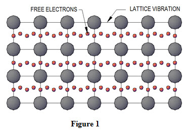
Solids: Solids generally consist of free electrons and atoms bound in periodic arrangement called lattice. Thermal conductivity in solids is attributed to migration of free electrons and lattice vibrations. Therefore, thermal conductivity of a solid is the sum of electronic component and lattice vibration component. Thermal conductivity of pure metals is high and contribution of electronic component is significant as compared to that of lattice vibration component as shown in Figure 1. Thermal conductivity of an alloy of two metals is considerably lower that that of either of two metals. For example values of thermal conductivity of copper and Nickel are 401 W/(m- oK) and 91 W/(m- oK) respectively where as thermal conductivity of constantan ( 55% copper and 45% Nickel) is only 23 W/(m- oK).
Arrangement of molecules in a material strongly affects the lattice component of thermal conductivity. Crystalline solid such as diamond has the highest value of thermal conductivity at room temperature. Thermal conductivity of solids generally decreases with increase in temperature.
Fluids: Solids generally have the highest value of thermal conductivity followed by liquids and gases on account of intermolecular spacing between the molecules. In solids molecules are closely packed, in liquids loosely packer and in gases very loosely packed. Thermal conductivity of gases increases with increase in temperature while that of liquids decreases with increase in temperature with glycerin and water being exceptions. Table 3 gives the values of thermal conductivity of different materials.
Table 3: Thermal Conductivity of Materials at Room Temperature
|
S. No. |
Material |
Conductivity, k ,W/(m-K) |
|
1. |
Diamond |
2300 |
|
2. |
Silver |
429 |
|
3. |
Copper |
401 |
|
4. |
Gold |
317 |
|
5. |
Aluminum |
237 |
|
6. |
Iron |
80.2 |
|
7. |
Glass |
0.78 |
|
8. |
Water |
0.607 |
|
9. |
Wood |
0.17 |
|
10. |
Air |
0.026 |
Objectives of conduction analysis:
The basic objective of conduction analysis is to determine the variation of temperature with respect to location and time throughout a body. The knowledge of temperature distribution with in a body is required to determine heat transfer rate. Location of a point with in a body, at which temperature is to be determined, is specified by choosing a suitable coordinate system amongst Cartesian coordinates, cylindrical coordinates or spherical coordinates. Temperature at a point is expressed as
- T (x, y, z, t) in rectangular or Cartesian coordinates for parallelepiped bodies
- T (r, φ, z, t) in cylindrical coordinates for cylindrical bodies
- T (r, φ, θ, t) in spherical coordinates for spherical bodies.
For any irregular shaped body, generally rectangular or Cartesian coordinates are used for conduction analysis.
(a) General Heat Conduction Equation in Cartesian Coordinates:
Consider flow of heat through a very small control volume oriented into three dimensional. The sides dx, dy and dz are parallel to x, y and z axes respectively as shown in Figure 2.
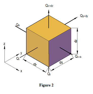
Let ‘T’ be the temperature of left face AEHD and it changes along x-direction. Let the temperature changes by amount ∂T through a unit distance ∂x and temperature gradient is expressed as ![]() . Similarly, change of temperature through distance dx will be
. Similarly, change of temperature through distance dx will be ![]() and temperature at the right face BFGC is
and temperature at the right face BFGC is ![]() . For non-isotropic materials, thermal conductivity changes as heat flows through the control volume. If Kx is the thermal conductivity at the left face AEHD, then quantity of heat flowing in to the control volume along x-direction through left face during time interval dt is expressed as
. For non-isotropic materials, thermal conductivity changes as heat flows through the control volume. If Kx is the thermal conductivity at the left face AEHD, then quantity of heat flowing in to the control volume along x-direction through left face during time interval dt is expressed as

Where, A is the area of the left face ADHD
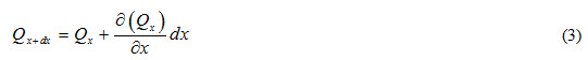
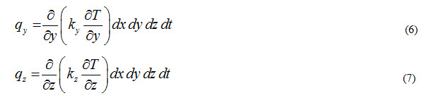
During same interval of time, heat flowing out of the right face BFGC along x-direction will be
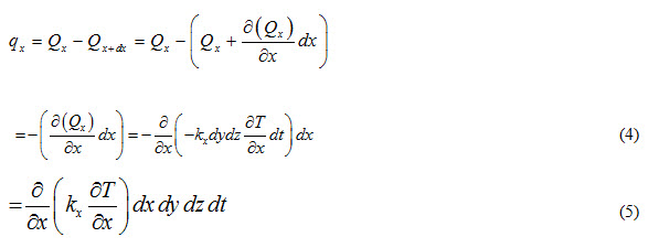
Heat accumulated in the control volume due to flow of heat along x-direction will be
Similarly, heat accumulated in the control volume due to heat flow along y and z directions can be expressed as
Let there is a heat source present inside the control volume which is generating ‘qg’ amount of heat per unit volume per unit time. Total heat generated in the control volume can be expressed as
![]()
Total heat accumulate in the control volume is the sum of equations (5), (6), (7) and (8) and it results in increase in the thermal energy of the control volume. This increase in thermal energy is reflected by rate of change of heat capacity of the control volume during given time interval ‘dt’ and is expressed as
= Mass of the control volume Χ specific heat Χ change of temperature of control
volume per unit time Χ Time interval
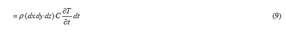
Heat Capacity or thermal capacity is defined as heat required to raise temperature of whole mass of a body by 1oC and is expressed as
= mass of a body Χ specific heat
From energy balance considerations, sum of equations (5), (6), (7) and (8) should be equal to equation (9).
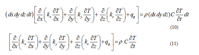
Equation (11) represents general conduction equation for three dimensional, unsteady heat flow through a non-isotropic material.
For homogeneous and isotropic materials, kx = ky = kz = k. Therefore, Equation (11) will become
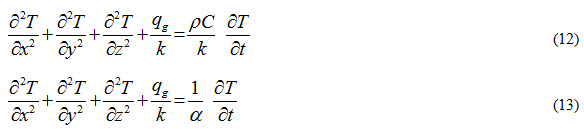
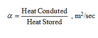
Where,  and is called thermal diffusivity of a material and it represents how quickly heat will propagate through a material. Thermal diffusivity is defined as ratio of heat conducted by a material to the heat stored by it per unit volume.
Heat will propagate more quickly in a material having higher value of thermal diffusivity and materials with smaller thermal diffusivity will store most of the heat.
Equation (13) is known as Fourier-Biot equation and can be written as
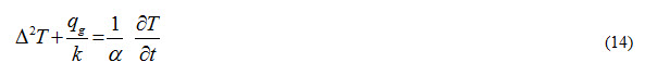
Δ2 is called Laplacian operator.
Different Cases:
i) If flow of heat is under unsteady state conditions and no heat generation within the control volume takes place, then qg = 0 and Equation (13) can be written as
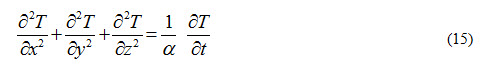
Equation (15) is known as diffusion equation
ii) If flow of heat is under steady state conditions, then temperature will not change with time and. Equation (13) can be written as
Equation (16) is known as Poisson equation
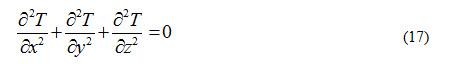
iii) If flow of heat is under steady state conditions without heat generation, Equation (13) can be written as

Equation (17) is known as Laplace equation
iv) For steady state and one-dimensional flow of heat through a body in which there is no heat generation, then Equation (13) can be written as
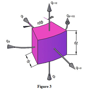
(b) General Heat Conduction Equation in Cylindrical Coordinates:
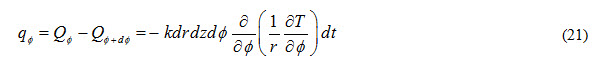
When conductive heat transfer occurs through bodies having cylindrical geometries such as rods, pipes etc., general conduction equation is derived in cylindrical coordinates. Let us consider a control volume having cylindrical dimensions (r, φ, z) and dr, dz and rd are the three sides of the control volume as shown in Figure 3.
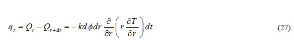
Heat inflow through (r, z) plane along direction is expressed as
Heat outflow through (r, z) plane along direction is expressed as
Heat accumulated in control volume due to flow through (r-z) plane during time interval dt is expressed as
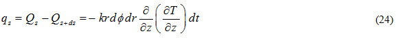
Heat inflow through (r,) plane along z-direction is expressed as
![]()
Heat outflow through (r,) plane along z-direction is expressed as
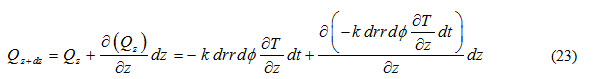
Heat accumulated in control volume due to flow through (r-) plane during time interval ‘dt’ is expressed as
Heat inflow through (z- ) plane along r-direction is expressed as

Heat outflow through (z-) plane along r-direction is expressed as
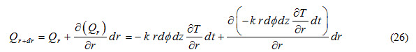
Heat accumulated in control volume due to flow through (z-) plane during time interval dt is expressed as
Let there is a heat source present inside the control volume which is generating qg amount of heat per unit volume per unit time. Total heat generated in the control volume can be expressed as
![]()
Total heat accumulate in the control volume is the sum of equations (21), (24), (27) and (28) and it results in increase in the thermal energy of the control volume. This increase in thermal energy is reflected by rate of change of heat capacity of the control volume during given time interval ‘dt’ and is expressed as
![]()
From energy balance considerations, sum of equations (21), (24), (27) and (28) should be equal to equation (29).
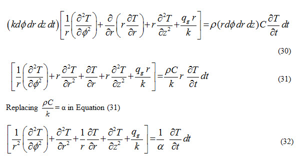
Equation (32) represents general conduction equation for three dimensional, unsteady heat flow in cylindrical coordinates.
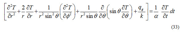
(C) General Heat Conduction Equation in Spherical Coordinates:
Similarly, the general conduction equation for geometries having spherical coordinates can be obtained and is expressed as:
Last modified: Friday, 14 March 2014, 9:56 AM