Site pages
Current course
Participants
General
Module 1. Basic Concepts, Conductive Heat Transfer...
Module 2. Convection
Module 3. Radiation
Module 4. Heat Exchangers
Module 5. Mass Transfer
Lesson 3. One dimensional steady state conduction through plane and composite walls, tubes and spheres without heat generation
One-Dimensional, Steady State Heat Conduction without Heat Generation:
i) Plane Wall or Slab of Uniform Conductivity without Heat Generation:
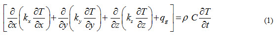
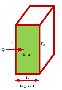
Consider steady state heat conduction through a plane wall of thickness ‘L’ and area ‘A’ having uniform conductivity ‘k’ as shown in Figure 1. Temperature on the left hand side of the wall is T1 and on the right hand side it is T2. Heat is flowing from left hand side to the right hand side as T1 is greater than T2. The general conduction equation which governs the conduction heat transfer is written as
Since it is a case of one-dimensional, stead heat conduction through a wall of uniform conductivity without heat generation, therefore, 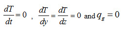 and
and
Therefore, equation (1) reduces to
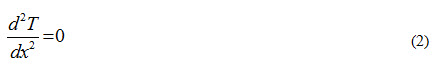
Equation (2) is used to determine the temperature distribution and heat transfer rate through the wall. Integrating equation (2) twice with respect to x, it can written as
T = C1 x + C2 (3)
Where, C1 and C2 are constants of integration.
Using the following boundary conditions:
i. At x = 0, T = T1
Equation (3) is written as C2 = T1 (4)
ii. At x = L, T = T2
Equation (3) can be written as T2 = C1 L + C2
Or T2 = C1 L + T1
C1= (T2 – T1)/L (5)
Substituting the values of C1 and C2 in equation (3)
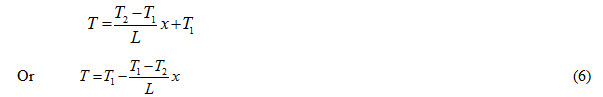
Equation (6) represents temperature distribution in the wall. It means temperature at any point along the thickness of the wall can be obtained if values of temperatures T1, T2, thickness L and distance of the point form either of the faces of the wall are known.
Rate of heat transfer can be determined by using Fourier’s law and can be expressed as

Integrating equation (6) with respect to x to obtain the expression for temperature gradient ![]()
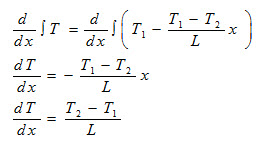
Substituting the value of ![]() from above equation in equation (7), we get
from above equation in equation (7), we get
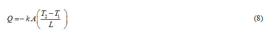
Equation (8) represents the heat transfer rate through the wall.
ii) Cylinder of Uniform Conductivity without Heat Generation:
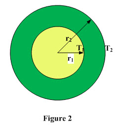
Consider steady state heat conduction through a cylinder having r1 and r2 as inner and outer radii respectively and length ‘L’ as shown in Figure 2. Temperature of the inner and outer surfaces is T1 and T2 respectively. Heat is flowing from inner to outer surface as T1 is greater than T2. The general conduction equation which governs the conduction heat transfer is written as
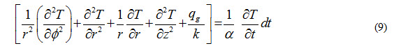
Since it is a case of one-dimensional, stead heat conduction through a wall of uniform conductivity without heat generation, therefore, 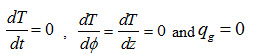
Therefore, equation (9) reduces to
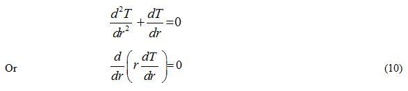
Equation (10) is used to determine the temperature distribution and heat transfer rate through the cylinder. Integrating equation (10) twice with respect to r, it can written as
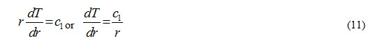
and T = C1 loge r + C2 (12)
Using the following boundary conditions:
i. At r = r1, T = T1
Equation (12) is written as T1 = C1 loge r1 + C2 (13)
ii. At r = r2, T = T2
Equation (12) can be written as
T2 = C1 loge r2 + C2 (14)
Subtracting equation (14) from equation (13), we get
T1 – T2 = C1 loge r1 – C1 loge r2
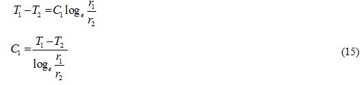
Substituting the values of C1 from equation (15) in equation (13)
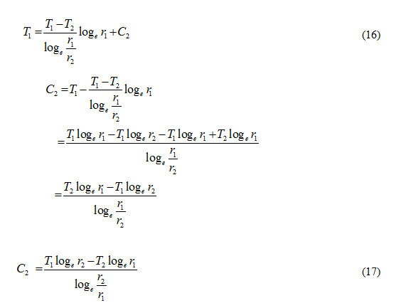
Substituting the values of C1 and C2 in equation (12), we get
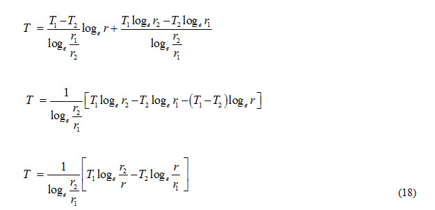
Equation (18) represents temperature distribution in the cylinder. Rate of heat transfer can be determined by using Fourier’s law and can be expressed as
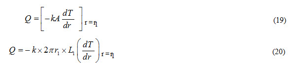
From equation (11) we can write
Substituting the value of C1 from equation (15), we can write

Substituting the value of from equation (21) in equation (20), we get
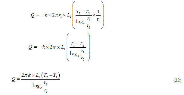
Equation (22) represents the heat transfer rate through the cylinder.
iii) Sphere of Uniform Conductivity without Heat Generation:
Consider steady state heat conduction through a hollow sphere having r1 and r2 as inner and outer radii respectively. Temperature of the inner and outer surfaces is T1 and T2 respectively. Heat is flowing from inner to outer surface as T1 is greater than T2. The general conduction equation which governs the conduction heat transfer is written as
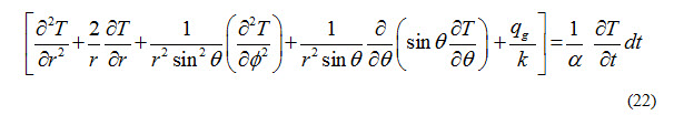
Since it is a case of one-dimensional, steady heat conduction through a shere without heat generation, therefore, 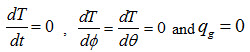
Therefore, equation (22) reduces to
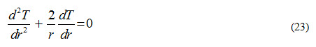
Multiplying both sides of equation (23) by r2 , we get
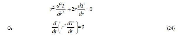
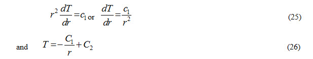
Equation (24) is used to determine the temperature distribution and heat transfer rate through the wall. Integrating equation (23) twice with respect to r, it can written as
Using the following boundary conditions:
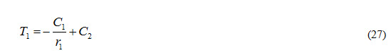
i. At r = r1, T = T1
Equation (26) is written as
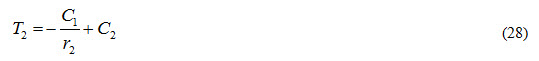
ii. At r = r2, T = T2
Equation (26) can be written as
Subtracting equation (28) from equation (27), we get
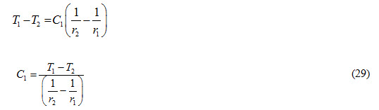
Substituting the values of C1 from equation (29) in equation (27)
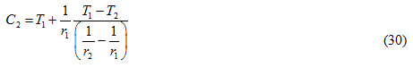
Substituting the values of C1 and C2 from equations (29) and (30) in equation (26)
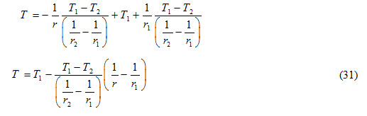
Equation (31) represents temperature distribution in a sphere. Rate of heat transfer can be determined by using Fourier’s law and can be expressed as
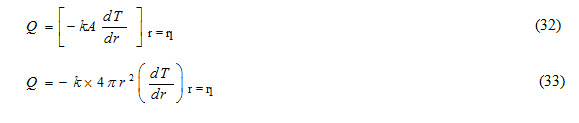
From equation (25) we can write
Substituting the value of C1 from equation (29), we can write 
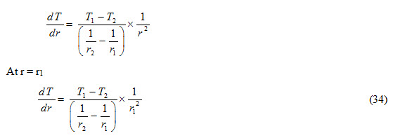
Substituting the value of ![]() from equation (34) from equation (33), we get
from equation (34) from equation (33), we get
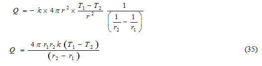
Equation (35) represents the heat transfer rate through a sphere.
Heat Flow through Composite Geometries:
A) Composite Slab or Wall:
Consider a composite slab made of three different materials having conductivity k1, k2 and k3, length L1, L2 and L3 as shown in Figure 3. One side of the wall is exposed to a hot fluid having temperature Tf and on the other side is atmospheric air at temperature Ta. Convective heat transfer coefficient between the hot fluid and inside surface of wall is hi (inside convective heat transfer coefficient) and ho is the convective heat transfer coefficient between atmospheric air and outside surface of the wall (outside convective heat transfer coefficient). Temperatures at inner and outer surfaces of the composite wall are T1 and T4 whereas at the interface of the constituent materials of the slab are T2 and T3 respectively.
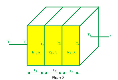
Heat is transferred from hot fluid to atmospheric air and involves following steps:
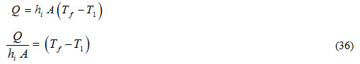
i) Heat transfer from hot fluid to inside surface of the composite wall by convection
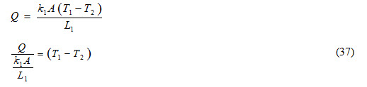
ii) Heat transfer from inside surface to first interface by conduction
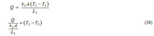
iii) Heat transfer from first interface to second interface by conduction
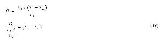
iv) Heat transfer from second interface to outer surface of the composite wall by conduction
v) Heat transfer from outer surface of composite wall to atmospheric air by convection
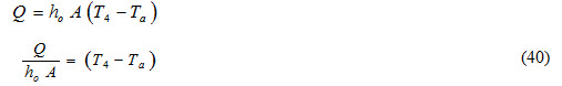
Adding equations (36), (37), (38) and (40), we get
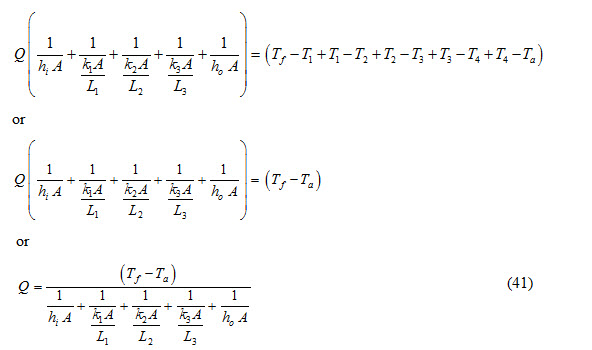
If composite slab is made of ‘n’ number of materials, then equation (41) reduces to
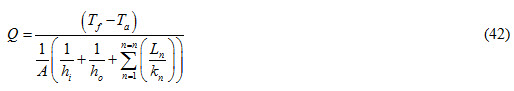
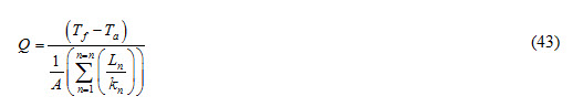
If inside and outside convective heat transfer coefficients are not to be considered, then equation (42) is expressed as
B) Composite Cylinder:
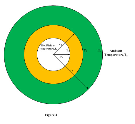
Consider a composite cylinder consisting of inner and outer cylinders of radii r1, r2 and thermal conductivity k1, k2 respectively as shown in Figure 4. Length of the composite cylinder is L. Hot fluid at temperature Tf is flowing inside the composite cylinder. Temperature at the inner surface of the composite cylinder exposed to hot fluid is T1 and outer surface of the composite cylinder is at temperature T3 and is exposed to atmospheric air at temperature Ta. The interface temperature of the composite cylinder is T2.. Convective heat transfer coefficient between the hot fluid and inside surface of composite cylinder is hi (inside convective heat transfer coefficient) and ho is the convective heat transfer coefficient between atmospheric air and outside surface of the composite cylinder (outside convective heat transfer coefficient). Heat is transferred from hot fluid to atmospheric air and involves following steps:
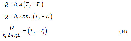
i) Heat transfer from hot fluid to inside surface of the composite cylinder by convection
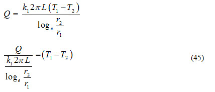
ii) Heat transfer from inside surface to interface by conduction
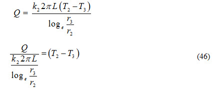
iii) Heat transfer from interface to outer surface of the composite cylinder by conduction
iv) Heat transfer from outer surface of composite wall to atmospheric air by convection

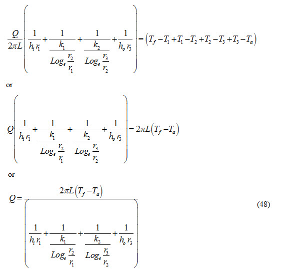
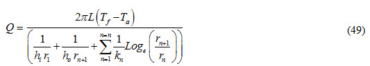
Adding both sides of equations (44), (45),(46) and (47), we get
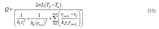
If the composite cylinder consists of ‘n’ cylinders, then equation (48) can be expressed as:
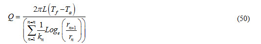
If inside and outside convective heat transfer coefficients are not to be considered, then equation (3.41) is expressed as
C) Composite Sphere:
Consider a composite sphere consisting of inner and outer cylinders of radii r1, r2 and thermal conductivity k1, k2 respectively. Hot fluid at temperature Tf is flowing inside the composite sphere. Temperature at the inner surface of the composite sphere exposed to hot fluid if T1 and outer surface of the composite cylinder is at temperature T3 and is exposed to atmospheric air at temperature Ta. The interface temperature of the composite cylinder is T2. Convective heat transfer coefficient between the hot fluid and inside surface of composite sphere is hi (inside convective heat transfer coefficient) and ho is the convective heat transfer coefficient between atmospheric air and outside surface of the composite sphere (outside convective heat transfer coefficient). Heat is transferred from hot fluid to atmospheric air and involves following steps:
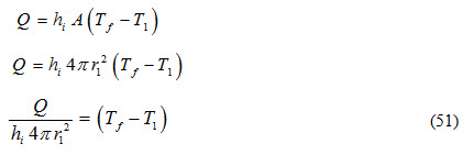
i) Heat transfer from hot fluid to inside surface of the composite sphere by convection
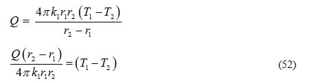
ii) Heat transfer from inside surface to interface by conduction.
iii) Heat transfer from interface to outer surface of the composite sphere by conduction
iv) Heat transfer from outer surface of composite wall to atmospheric air by convection
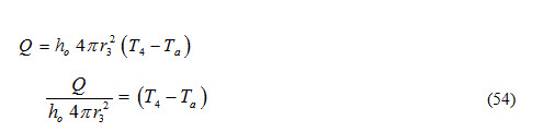
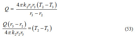
Adding both sides of equations (51), (52),(53) and (54), we get
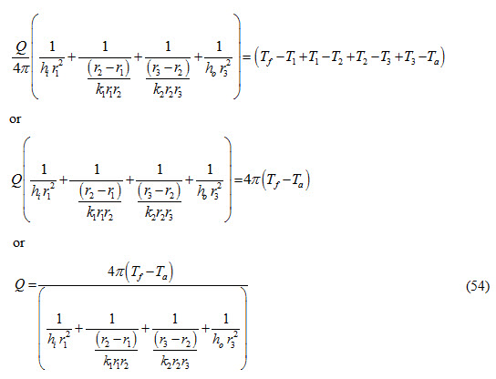
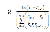
If the composite sphere consists of ‘n’ concentric spheres, then equation (54) can be expressed as:
If inside and outside convective heat transfer coefficients are not to be considered, then equation (55) is expressed as
Last modified: Friday, 14 March 2014, 11:36 AM