Site pages
Current course
Participants
General
Module 1. Basic Concepts, Conductive Heat Transfer...
Module 2. Convection
Module 3. Radiation
Module 4. Heat Exchangers
Module 5. Mass Transfer
Lesson 6. Numericals on conduction
Example 3.20 Determine the heat transfer rate across a composite slab which is made of different materials with top and bottom as shown in fig. 3.16. The entire left-hand face is held at the temperature T1 while the entire right hand face is at the temperature T2. The conductivities of the two different materials are stated as ka and kb, and their areas as viewed in the direction of slab thickness δ are Aa and Ab respectively. Steady state exists, there is no heat generation and the slab is so thin that any edge effects can be neglected. Interpret the result in terms of an electrical circuit.
Solution: Applying Fourier law of heat conduction separately to materials a and b, we obtain
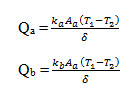
The desired quantity of heat transfer through the slab equal the sum of Qa and Qb
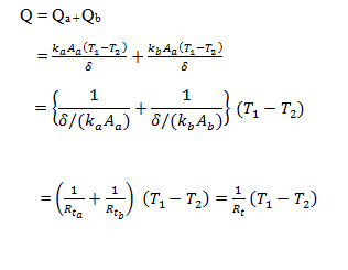
Apparently, the two thermal resistances
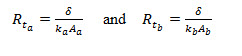
Appear in the same way as two electrical resistors in parallel. Accordingly the electrical circuit for the heat transfer through the given composite slab will be as indicated in fig. 3.16.
Example 3.20 Find the heat flow rate through the composite wall as shown in fig.3.17. Assume one-dimensional flow and take
Ka =150 W/m-deg; kb = 30 W/m-deg; kc = 65 W/m-deg; kd = 50 W/m-deg
Solution: The equivalent thermal circuit for heat flow in the composite system has been shown in fig. 3.18.
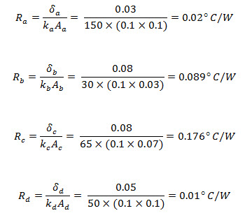
The resistances Rb and Rc are in parallel and their equivalent resistance Req is
![]()
The equivalent resistance is now in series with resistance Ra and Rd. The total thermal resistance for the entire circuit then becomes
∑ Rt=Ra + Req + Rb
=0.02+0.1469+0.1 =0.2669°C/W
Hence heat transfer rate through the system is
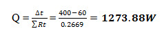
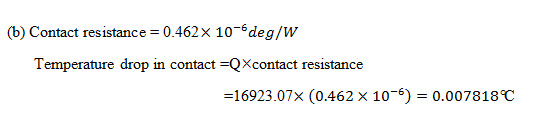
Example 3.24 Two slabs, each 200 mm thick and made of materials with thermal conductivities of 16 W/m-deg and 1600 W/m-deg, are placed in contact which is not perfect. Due to roughness of surfaces, only 40% of area is in contact and air fills 0.02 mm thick gap in the remaining area. If the extreme surfaces of the arrangement are at temperatures of 250° C and 30° C, determine the heat flow through the composite system, the contact resistance and temperature drop in contact.
Take thermal conductivity of air as 0.032 W/m-deg and assume that half of the contact (of the contact area) is due to either metal.
Solution: Refer fig. 3.22 for the composite system and its equivalent thermal resistance
The various thermal resistances to flow of heat are:
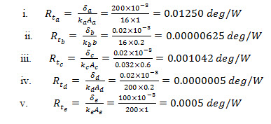
The resistances , and are in parallel and their equivalent resistance (Rt)eq is
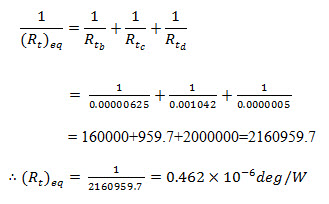
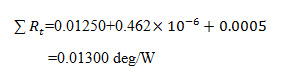
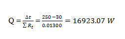
This equivalent resistance is now in series with resistance and . The total thermal resistance for the entire circuit then becomes
Hence, heat transfer rate through the system is
Example 3.34 A glazed window, made of 8mm thick glass of thermal conductivity 1.5 W/mK, has its outside surface maintained at 5°C so that frosting is reduced. The surroundings are at-10°C with convective coefficient 55 W/m2K.the desired condition is attained by providing a uniform heat flux at the inner surface of the window which is fitted into a room where the air temperature is 25° with convection of 12.5 W/m2K. Make calculations for the heating required per m2 area.
Solution: Refer fig.3.35 for the window fixture with specified data and thermal circuit for the resistance involved.
Let t1 be the temperature at the heater. Under steady state conditions heat conducted through the glass barrier equals the heat convected through the outde film. That is
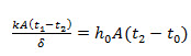
Considering unit area,
![]()
That gives:
(b) From energy balance
Heat flow (Q) + heat received by convection fram room (Q2)
= heat conducted through the glass barrier (Q1)
or heat flux Q = Q1 – hi A (ti –t1)
=825-12.51(25-9.4)= 630 W
Thus, the heat required per m2 area is 630W.
Example 3.34 A square plane heater of 0.8 kW rating and measuring 15cm15cm is placed between two slabs A and B and the following data refers to these slabs:
Slab A is 1.8 cm thick with k = 55 W/m-deg
Slab B is 1cm thick with k = 0.2 W/m-deg
The outside heat transfer coefficients on the side of plate A and B are 200 W/m2-deg and 45 W/m2-deg respectively. If the surrounding environment is at 27°C temperature, make calculations for the maximum temperature of the system and outside surface temperature of both slabs.
Solution: Refer fig. 3.36 for the arrangement and thermal resistance network for the system.
The individual resistances are evaluated as:
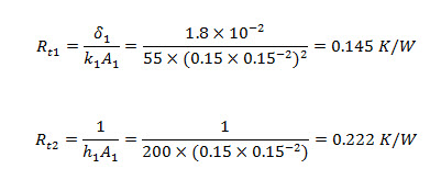
These resistances are in series and accordingly for slab A (left branch of the circuit)
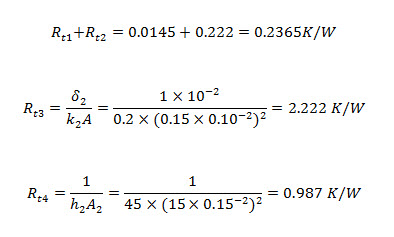
These resistances are in series and accordingly for slab B (right branch of the circuit)
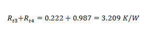
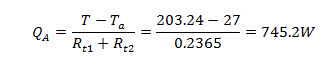
(a) Rating of Heater, Q = QA+ QB
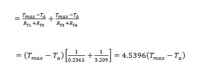
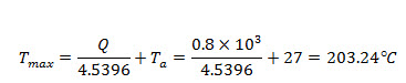
Maximum temperature in the system,
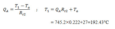
(b) Considering left side branch of the circuit (slab A)
If T1 is the temperature at exposed surface of slab A, then
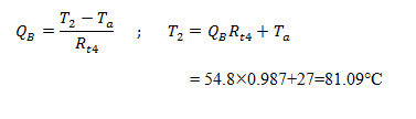
Considering right side branch of the circuit (slab B)
Example 3.47 The hot combustion gases at 300°C flow through a hollow cylindrical pipe of 10cm inner diameter and 12 cm outer diameter. The pipe is located in a space at 30°C and the thermal conductivity of the pipe material is 200 W/mK. Neglecting surface heat transfer coefficients, calculate the heat loss through the pipe per unit length and the temperature at a point halfway between the inner and outer surface. What should be the surface area normal to the direction of heat flow so that the heat transfer through the pipe can be determined by considering material of the pipe as a plane wall of the same thickness?
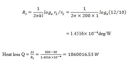
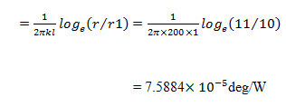
Solution: In terms of geometrical parameters, thermal resistance of a pipe is
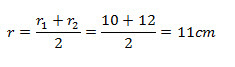
(ii) Radius at halfway through the pipe wall,
Thermal resistance of cylindrical pipe upto its mid-plane
Since heat flow through each section is same;
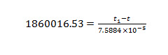
Temperature at the mid plane,
![]()
Alternatively from the expression for temperature distribution
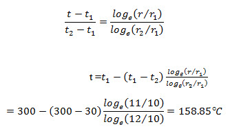
(iii) The equivalent logarithmic mean area is
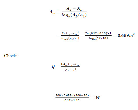
This is approximately same as calculated above.
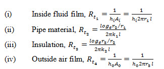
Example 3.54 A steel pipe of 20 mm inner diameter and 2mm thickness is covered with 20mm thick of fibre glass insulation (k= 0.05 W/m-deg). If the inside and outside convective coefficients are 10 W/m2-deg and 5 W/m2-deg, calculate the overall heat transfer coefficient based on inside diameter of the pipe.
Solution: r1=10mm ; r2 = 10+2=12mm ; r3 = 12+20=32mm
The thermal resistances to flow of heat are offered by
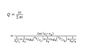
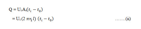
The heat transfer through the insulated pipe is than given by
The thermal conductivity of steel pipe is not given, and generally it is much higher than that of insulation. Accordingly thermal resistance due to pipe material can be neglected.
That gives:
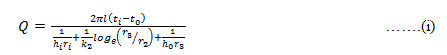
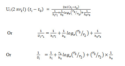
If Ui is overall heat transfer coefficient based on inside area of the steel pipe, then heat flow rate can also be written as
Comparing identities (i) and (ii), we note that
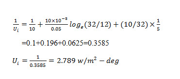
Upon substitution of given data,
Example 3.58 A 3 cm diameter pipe at 100°C is losing heat at the rate of 100 W per metre length of pipe to the surrounding air at 10°C. This is to be reduced to a minimum value by providing insulation. The following insulation materials are available:
Insulation A
Quantity =3.15per metre length of pipe
Thermal conductivity = 5W/m-deg
Insulation B
Quantity =4per metre length of pipe
Thermal conductivity = 1 W/m-deg
Examine the position of better insulating layer relative to the pipe. What percentage saving in heat dissipation results from that arrangement?
Solution: Thermal resistance due to pipe material works out as
For a pipe with two layers of insulation,
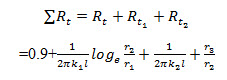
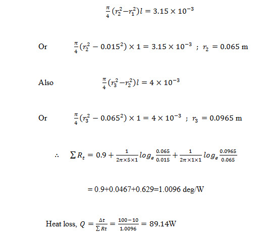
1st Arrangement : The insulation material A is placed inside, i.e., next to the pipe
2nd Arrangement : The insulation material B is placed inside, i.e., next to the pipe
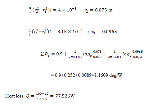
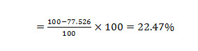
Obviously the heat loss is small when the insulation material B is placed next to pipe.
Saving in the heat loss
Example 3.63 Two insulation materials A and B, in powder form, with thermal conductivities of 0.005 W/m-deg and 0.03 W/m-deg were purchased for use over a sphere of 50 cm diameter. Material A was to form the first layer 4 cm thick and material B was to be the next layer 5 cm thick. Due to ovetsight during installation, whole of material B was applied first and subsequently there was a layer formed by material A. Investigate how the conduction heat transfer would be affected.
Solution: Case I r1=0.2 m ; r2 = 0.24 m ; r3 = 0.29 m
Thermal resistance to heat flow ,
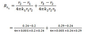
=13.27+1.906=15.176°C/W
Case II : When the materials get interchanged, there would be change in radii also.
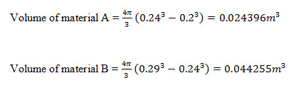
The new radii are then worked out as
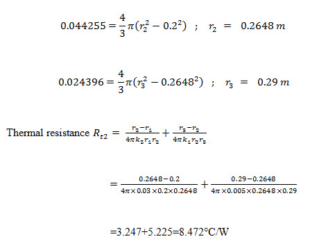
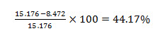
Heat transfer is inversely proportional to thermal resistance. As such the heat flow will increase by
Example 3.65 A 6.5m diameter vertical kiln has a hemi-spherical dome at the top; the dome is fabricated from a 25 cm thick layer of chrome brick which has a thermal conductivity of 1.16 W/m-deg. The kiln dome has inside temperature of 875°C and 10°C atmospheric air result into 11.4 W/m2-deg heat transfer coefficient between the dome and air. Estimate the outside surface temperature of the dome and the heat loss from kiln. Compare this heat with that would result from a flat dome fabricated from the same material and with kiln operating under identical temperature conditions.
Solution: Conduction heat loss through from a spherical body is given by
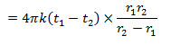
And for a hemi-sphere it equals half of this value.
Conduction heat loss the hemi-spherical dome,
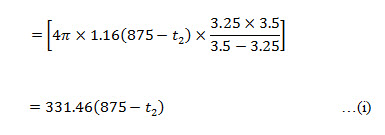
Convective heat flow from outside surface of dome to the surrounding air,
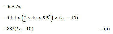
Under Steady state conditions,
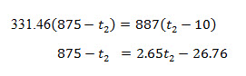
Temperature at the outside surface of the dome,
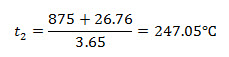
The heat loss from the dome may now be obtained from either of the expression (i) and (ii).
Q = 331.46(875-247.05) = 208140.307
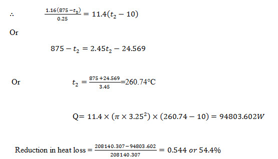
(b) For a dome with flat top:
![]()
The area for conduction and convection heat flow will be same
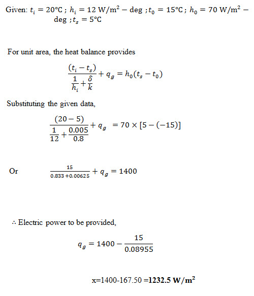
Example 4.1 The rear window of an automobile is made of 5 cm thick glass of thermal conductivity 0.8 W/m-deg. To defrost this window, a thin transparent film type heating element has been fixed to its inner surface. For the conditions given below, determine the electric power that must be provided per unit area of window if a temperature 5°C is maintained at its outer surface.
Interior air temperature and the corresponding surface coefficient,= 20°C and 12 W/m2-deg. Surrounding air temperature and the corresponding surface coefficient,= -15°C and 70 W/m2-deg.
Electric heater provides uniform heat flux.
Solution:
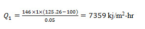
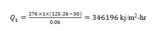
Example 4.2 A composite slab consists of 2 cmthick layer of steel (k=146 kj/m-hr-deg) on the left side and a 6 cm thick layer of brass (k = 276 kj/m-hr-deg) on the right hand side. The outer surfaces of the steel and brass layer are maintained at 100° and 50° respectively. The contact between the two slab is perfact and heat is generated at the rate of 4.2 105 kj/m2-hr at the plane of contact. The heat thus generated is dissipated from both sides of composite slab for steady state conditions. Calculate the temperature at the interface and heat flow through each slab.
Solution: Let ti be the temperature at the interface. Under stipulation for heat dissipation from both sides,
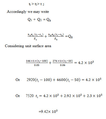
Temperature at the interface,
![]()
Heat transfer through the steel layer,
Heat transfer through the brass layer,
Example 4.7 A long stainless steel bar 20mm 20mm in square cross-section is perfectly insulated on three sides and is maintained at a temperature of 400°C on the remaining side. Determine the maximum temperature in the bar when it is conducting a current of 1000 ampere. Take thermal and electrical conductivities of steel as 16 W/m-deg and 1.5 /ohm-cm and neglect the edge effects. Also work out the heat flow the bar.
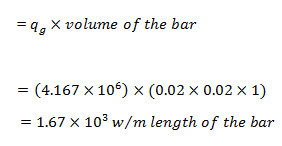
Solution: The heat generated per unit volume due to flow electric current is worked out from the relation.
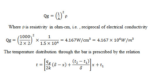
Maximum temperature occurs at the centre, i.e. , at Further under the given boundary conditions: Therefore,
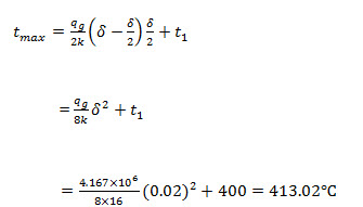
Under steady state conditions, the heat flow through the bar equals the heat generated within it
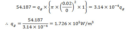
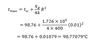
Example 4.21 A stainless steel wire (conductivity = 20 W/m-deg and resistivity=70 micro ohm-cm) of length 2 m and diameter 2.5 mm is submerged in a fluid at 50°C and an electric current of intensity 300 amps passes through it. If conductance at the wire surface is 4 kW/m2-deg, workout the steady state temperature at the centre and at the surface of the wire.
Solution:
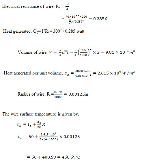
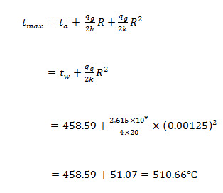
Maximum temperature in the wire occurs at its geometric centre line, and can be computer from the relation,
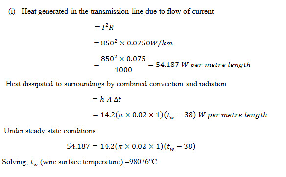
Example 4.24 A 66 V transmission line carrying a current of 850 ampere is 20 mm in diameter and electrical resistance of the copper conductor is 0.075 ohm/km. Assuming that the surrounding are at 38°C and that the combined convection and radiation coefficient for heat transfer from the wire surface to the surroundings is 14.2 W/m2 K, make calculations for:
(i) Surface temperature of the transmission line
(ii) Rate of heat generation per unit volume of the wire.
(iii) Maximum temperature in the line.
The thermal conductivity of copper is 400 W/mK.
Solution
(ii) Let qg be the volumetric heat generated at uniform rate over the wire cross-section
(iii) Maximum temperature in the wire will occur at the geometric centre line of the wire and may be computed from the relation,
The small difference between surface and centre temperature results from the relatively small heat generation rate and the high thermal conductivity of copper.
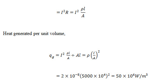
Example 4.26 An internally copper conductor of 2 cm outer radius and 0.75 cm inner radius carries a current density of 5000amp/cm2. A constant temperature of 70° C is maintained at the inner surface and there is no heat transfer through insulation surrounding the copper. Set up an equation for temperature distribution through copper. Proceed to calculate the maximum temperature of copper and the radius at which it occurs. Also find the internal heat transfer rate and check that this equals the total energy generation in the conductor.
For copper: thermal conductivity k= 380 W/m-deg and the resistivity
Solution Total volumetric heat generation,
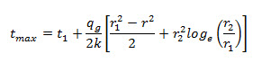
For steady state conditions, the radial temperature distribution for a hollow cylinder with outside surface insulated is given by
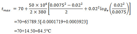
The maximum temperature occurs at the insulated surface, i.e. ,at the outer radius and it equals
Inserting the appropriate values,
The internal heat transfer rate can be obtained by finding the temperature gradient at the inner radius, i.e., at r = 0.0075m and then invoking the Fourier’s law of heat conduction.
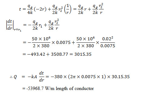
The –ve sign indicates that the heat flow is radially inwards.
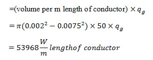
Check: Since the outer surface is insulated, the entire heat generated within the conductor must be dissipated internally. Therefore the internal heat transfer must be
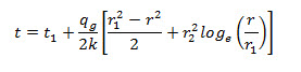
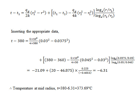
Example 4.29 A hollow cylinder of 3 cm inner radius and 4.5 cm outer radius has a heat generation rate of . The inner and outer surfaces are maintained at temperatures of 380°C and 360°C respectively and thermal conductivity of the cylinder material is 20 W/m-deg. Make calculations for the temperature at mid radius.
Solution r1=0.03 m ; r2 = 0.45 m ; and r3 = 0.0375 m at mid radius
For the specified boundary conditions, the temperature distribution is given by
Last modified: Saturday, 15 March 2014, 11:00 AM