Site pages
Current course
Participants
General
Module 1. Basic Concepts, Conductive Heat Transfer...
Module 2. Convection
Module 3. Radiation
Module 4. Heat Exchangers
Module 5. Mass Transfer
Lesson 8. Insulation materials, critical thickness of insulation and Numerical Problems
HEAT TRANSFER FROM EXTENDED SURFACES
Fins: Heat transfer from a hot surface to surrounding fluid takes place by convection and is governed by Newton’s law of cooling
Q = h A (Ts – Tf) (1)
It is obvious from above equation that heat transfer rate can be enhanced by increasing
Either by increasing convective heat transfer coefficient, h.
Or by increasing area of heat transferring surface, A.
Or by increasing temperature difference, (Ts – Tf)
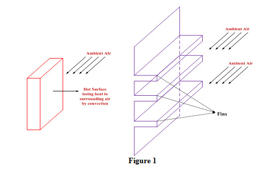
Heat transfer rate is generally enhanced by increasing area of heat transferring surface as shown in Figure 1. It is not possible always to increase the value of convective heat transfer coefficient, h, by increasing velocity of flow of fluid surrounding the hot surface or to increase temperature difference by lowering temperature of fluid which is in contact with the hot surface.
Increase in heat transfer area is achieved by attaching protrusions to hot solid surface. These protrusions are referred as fins or spines and are made of materials having high thermal conductivity such as aluminum. Fins bring about considerable enhancement in heat transfer rate from a solid surface by exposing a larger surface area for convective and radiative heat transfer.
Fin Applications:- Fins are generally used when convective heat transfer coefficient is low such as in case of gases and under natural convection. There are numerous appliances used by us in daily life in which fins have been used to enhance heat transfer rate.
Electrical apparatus like transformers and motors
Engines of scooters, motorcycles and compressors The circumferential fins of rectangular or triangular profile are commonly used on the engine cylinders of scooters and motor cycles
Condenser and evaporators of a refrigerating systems
Car radiator
Types of Fins:
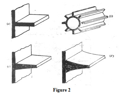
Straight Fin: The terms straight fin is applied to the extended surface attached to a wall which is otherwise plane. Figures 2 (a) and (b) are of fins of uniform area whereas Figures (c) and (d) are of fins of non-uniform area.
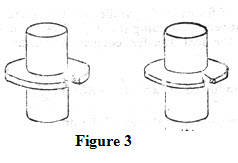
Annular(circumferential) fin: Annular fin is one, attached circumferentially, to a cylindrical surface as showon in Figure 3.
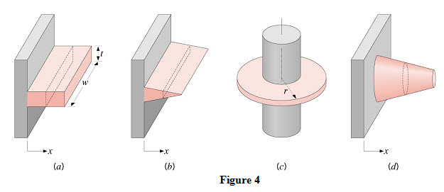
3. Spine or pin fin: It is an extended surface of cylindrical or conical shape as shown in Figure 4.
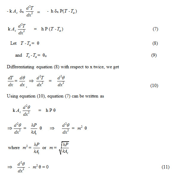
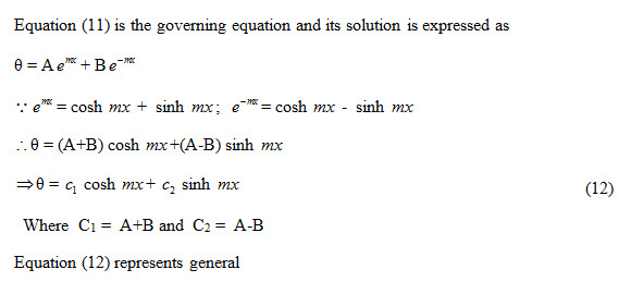
Heat transfer through a fin of uniform cross-section
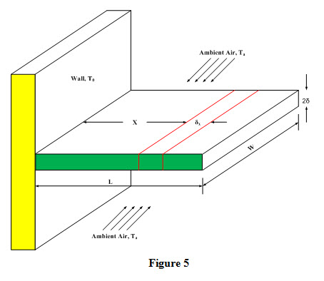
The purpose of heat transfer analysis trough a fin is to determine the increases in heat transfer obtained by attaching fins to a surface. In order to increase heat transfer from a plane wall, a rectangular fin of length ‘L’, width ‘w’ and thickness ‘2δ’ has been attached to the wall as shown in Figure 5. Heat flows along the length of the fin and it is surrounded by atmospheric air at temperature Ta. Temperature at the base or root of fin adjoining the wall is To.
In order to simplify the analysis, following assumptions have been made
Flow of heat takes place under steady state conditions and is one dimensional i.e. along the length of fin.
Thermal conductivity of fin material is constant.
Convective heat transfer coefficient ‘h’ is uniform over the entire surface of fin.
Temperature, To, at the base or root of fin is uniform and is equal to wall temperature Tw.
Consider a small element of thickness ‘δx’ at a distance ‘x’ from the base of fin and its perimeter and cross-sectional area are expressed as
Perimeter, P = 2w + 4δ = 2 ( w + 2 δ )
Cross-sectional area, Ac = w
Surface Area, A = P δx
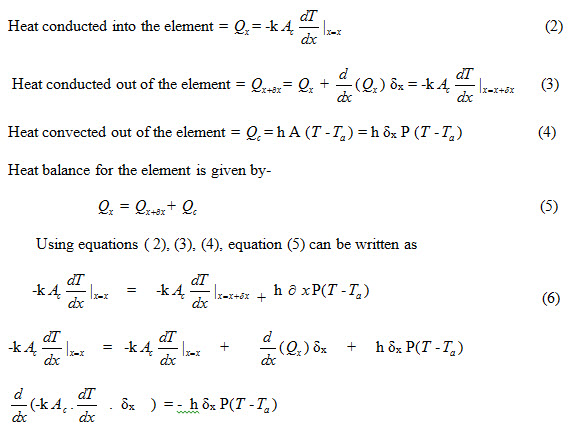
Under steady state conditions, energy balance on this element can be expressed as
Rate of heat conducted in to = Rate of heat conducted = Rate of heat convected
the element at x from the element at x+ δx from the element
Last modified: Tuesday, 18 March 2014, 5:13 AM