Site pages
Current course
Participants
General
Module 1: Fundamentals of Reservoir and Farm Ponds
Module 2: Basic Design Aspect of Reservoir and Far...
Module 3: Seepage and Stability Analysis of Reserv...
Module 4: Construction of Reservoir and Farm Ponds
Module 5: Economic Analysis of Farm Pond and Reser...
Module 6: Miscellaneous Aspects on Reservoir and F...
Lesson 11 Seepage through Dam
11.1 Definition and Basic Concept
11.1.1 Seepage through Earthen Dams
Wet areas downstream of the dams are not natural springs, rather seepage through or under the dam. Even if natural springs exist, they should be treated with suspicion and carefully observed. Flows from groundwater springs in existence prior to the reservoir would probably increase due to the pressure caused by the pool of water behind the dam.
All dams have some seepage as the impounded water seeks paths of least resistance through the dam and its foundation. Seepage becomes a concern when it carries sediments (silt particles) with it, and so, should be controlled to prevent erosion of the embankment or foundation or damage to concrete structures.
11.1.2 Detection of Seepage
Seepage can emerge anywhere on the downstream face, beyond the toe, or on the downstream abutments at elevations below normal pool. Seepage may vary in appearance from a soft wet area to a flowing spring. It may show up first as an area where the vegetation is lush and darker green. Cattails, reeds, mosses, and other marsh vegetation often become established in a seepage area. Another indication of seepage is the presence of rust coloured iron bacteria. Due to their nature, the bacteria are found more often where water is discharging from the ground than in surface water. Seepage sometimes makes inspection and maintenance difficult. It can also saturate and weaken the portions of the embankment and foundation, making the embankment susceptible to earth slides.
If the seepage forces are large enough, soil will be eroded from the foundation of the dam and deposited in the shape of a cone or boil around the outlet. When these boils appear, professional advice needs to be taken immediately. Seepage flow, when looks muddy due to carrying of sediment, is an evidence of piping below the foundation. It is a serious problem as far as safety of the dam is concerned. In case it is left unnoticed, it leads to failure of the dam. Piping can most often occur along a spillway or other conduit through the embankment, and these areas should be closely inspected. Sinkholes may develop on the surface of the embankment as internal erosion takes place. A whirlpool in the lake surface may follow a rapid and complete failure of the dam. Emergency procedures, including downstream evacuation, should be implemented immediately if any of these conditions are noticed.
Seepage can also develop under or downstream of the concrete structures such as chute spillways or headwalls. When the concrete structure does not have the provision of weep holes or relief drains to relieve the water pressure, the concrete structure may heave, rotate, or crack. The effects of the freezing and thawing can amplify these problems. It should be noted that the water pressure behind or beneath structures may also be due to infiltration of surface water or spillway discharge, but should still be addressed.
A continuous or sudden drop in the normal lake level is another indication that seepage is occurring. In this case, one or more locations of flowing water are usually noted downstream from the dam. This condition, in itself, may not be a serious dam safety problem, but will require frequent and close monitoring through professional assistance.
11.1.3 Seepage Control
The need for seepage control in dams depends on the quantity, content, and location of the seepage. It is not usually attempted unless the seepage has lowered the pool level or is endangering the dam or appurtenant structures.
However, reducing seepage that occurs after the construction of the dam is difficult and expensive. Typical methods used to control the quantity of seepage are grouting and/or installation of an upstream blanket. Of these methods, grouting is probably the least effective and is most applicable to leakage zones in bedrock, abutments, and foundations. These methods must be designed and constructed under the supervision of a professional engineer having expertise in construction of dams.
Controlling the content of the seepage or preventing seepage flow from soil particles is extremely important. Modern design practice incorporates the control of seepage into the dam design through the use of cutoffs, internal filters, and adequate drainage provisions. Control at points of seepage exit can be accomplished after construction by installation of toe drains, relief wells, or inverted filters.
Weep holes and relief drains can be installed to relieve water pressure or drain seepage from behind or beneath concrete structures. These systems must be designed to prevent migration of soil particles but still allow the seepage to drain freely. The design of toe drains, relief wells, inverted filters, weep holes, or relief holes is to be made by an expert as regular monitoring of these features is critical.
11.1.4 Monitoring
Regular monitoring is essential to detect seepage and prevent dam failure. Knowledge of the dam's history is important to determine whether the seepage condition is in a steady or varying state. It is important to keep written records of points of seepage exit, quantity and content of flow, size of wet area, and type of vegetation for comparison. Photographs taken at the time of inspection are excellent records for understanding the gravity of seepage. All records should be kept with the Inspection and Maintenance Plan of the dam. The inspector should always look for the increase in flow and the evidence of soil particles carried with the flow as they indicate the seriousness of the problem.
Instruments may also be used to monitor seepage. Triangular weirs like V-notch can be used to measure flow rates and piezometers installed within the embankment may provide information about the saturation level or phreatic surface through the dam.
Regular surveillance and maintenance of the internal embankment and foundation drainage outlets is also required. The rate and content of flow from each pipe outlet for toe drains, relief wells, weep holes, and relief drains should be monitored and documented regularly. Normal maintenance consists of removing all obstructions from the pipe to allow free drainage of water. Typical obstructions include debris, gravel, sediment, mineral deposits, and calcification of concrete and rodent nests. Water should not be permitted to submerge the pipe outlets for a prolonged period. It inhibits the inspection and maintenance of the drains and sometimes, clogs them. Rodent guards are readily available and should be used wherever necessary.
11.2 Darcy's Law
Darcy's law was formulated by Henry Darcy based on the results of experiments on the flow of water through beds of sand. It enunciatesa generalized relationship for flow of liquid in porous media. It shows that the volumetric flow rate is a function of the cross sectional area of flow, the hydraulic gradient and a proportionality constant. It may be stated in different forms depending upon the flow conditions. The law has been found valid for any Newtonian fluid. As it was established under saturated flow conditions, so it requires necessary adjustment when applied for unsaturated condition and multiphase flow. The following sections outline its common forms and assume water as the working fluid unless otherwise stated.
11.2.1 One-Dimensional Flow
Simple Discrete Form
For a finite one dimensional (1-D) flow as presented in Fig. 11.1, it may be stated that,
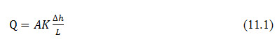
Where, Q = volumetric flow rate (m3/s or ft3/s); A = flow area perpendicular to L (m2 or ft2); K = hydraulic conductivity (m/s or ft/s); l = flow path length (m or ft); h = hydraulic head (m or ft); and Δh = the change in h over the path L.
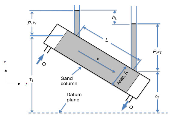
Fig. 11.1. One dimensional flow through sand column.
(Source: http://biosystems.okstate.edu/darcy/laloi/basics.html)
The hydraulic head, h, at a specific point is the sum of the pressure head and the elevation
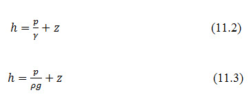
Where, p = water pressure (N/m2); = unit weight of water (N/m3); = density of water (kg/m3);g = acceleration due to gravity (m/s2 ); and z = elevation (m or ft).
While Eq.11.2 is the usual form used in English units, Eq. 11.3 is the normal SI form of the equation. The hydraulic head is the height that water that would rise in a piezometer. Thus, Δh in Eq. 11.1 is simply the difference in height of water in piezometers placed at the inlet and the outlet (Δh = hinlet-houtlet). Substituting the value of, h, in Eq.11.3 into Eq.11.1 yields,
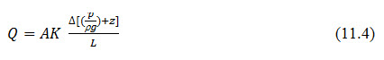
Eq. 11.4 is approximately the form used in Darcy’s law to analyze the experimental data. Note that the flow is not a function of the absolute pressure or the elevation; rather it is only a function of the change in hydraulic head.
Differential Form
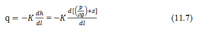
A more general form of the Eq.11.4 results when the limit of Δh with respect to the flow direction l, as the flow path L goes to zero. Applying that step to equations 11.1 and 11.4 yields,

The minus sign on the right hand term reflects that the hydraulic head always decreases in the direction of flow.
11.3 Flow Variables
11.3.1 Darcy Flux
The Darcy flux is defined as,
Where, q = Darcy flux (ms-1 or fts-1).
The Darcy flux is the volumetric flow per unit area. Substitution of equation 11.6 into 11.5 yields,
11.3.2 Seepage Velocity
While the Darcy flux has the units of velocity, it is not the velocity of the water in the pores. The solid matrix takes up some of the flow area. The average pore water velocity is termed as the seepage velocity, v, and is given by
Where, f = Porosity of the porous media. The maximum pore velocity is a function of the pore geometry and cannot be easily predicted except for regular shapes. In circular tubes, the maximum velocity is almost double of ‘v’.
11.3.3 Transmissivity
In saturated groundwater analysis with nearly horizontal flow, it is a common practice to combine the hydraulic conductivity and the thickness of the aquifer into a single variable.
Where, T = Transmissivity (m2s-1 or ft2s-1); and b = thickness of aquifer (m).
11.3.4 Permeability
When the fluid is other than water at standard conditions, the conductivity is replaced by the permeability of the media. The two properties are related by,
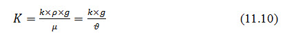
Where, k = permeability, (m2 or ft2); = fluid absolute viscosity, (N s/m2 or lb s/ft2); and = fluid kinematic viscosity, (m2/s or ft2/s).
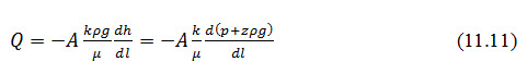
Ideally, the permeability of a porous media is the same to different fluids. Thus, the flow of one fluid can be predicted from the measurement of a second with Eq.11.10. However in practice, the solid matrix may swell or sink with different fluids and produce different values of k. Substitution of Eq.11.10 into 11.5 yields,
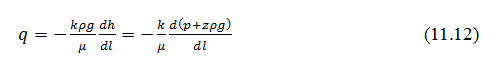
Likewise, substitution into Eq. 11.7 produces,
11.4 Laplace's Equation of Continuity
In the preceding section, we considered the application of Darcy's law to compute the flow of water through soil. In many instances the flow of water through soil is not in one direction only, nor is it uniform over the entire area perpendicular to the flow. In such cases, the water flow is generally calculated by the use of graphs referred to as flow nets. The concept of the flow net is based on Laplace's equation of continuity, which governs the steady flow condition for a given point in the soil mass.
To derive the Laplace differential equation of continuity, let us consider a single row of sheet piles that have been driven into a permeable soil layer as shown in Fig. 11.2(a).The row of sheet piles is assumed to be impervious. The steady state flow of water from the upstream to the downstream side through the permeable layer is a two dimensional flow. For flow at a point A, we consider an elemental soil block. The block has dimensions dx, dy, and dz (length dy is perpendicular to the plane of the paper);
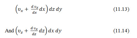
The soil block is shown in an enlarged scale in Fig.11.2b. Let ʋx, and ʋz be the components of the discharge velocity in the horizontal and vertical directions, respectively. The rate of flow of water into the elemental block in the horizontal direction is equal to ʋxdzdy, and in the vertical direction it is ʋzdxdy. The rates of outflow from the block in the horizontal and vertical directions are, respectively,

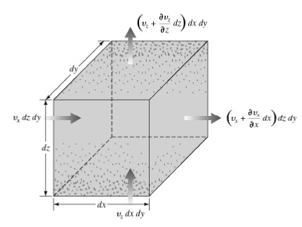
(b)
Fig. 11.2. (a) Single-row sheet piles driven into permeable layer; (b) flow at a.
(Source:http://faculty.uml.edu/ehajduk/Teaching/14.333/documents/14.3332013FlowNets.pdf)
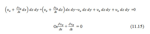
Assuming that water is incompressible and that no change of volume in the soil mass occurs, the total rate of inflow should be equal the total rate of outflow. Thus,
With Darcy's law, the discharge velocities can be expressed as
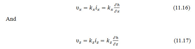
Where, and are the hydraulic conductivities in the vertical and horizontal directions, respectively.
From Eqs.11.15, 11.16 and 11.17, we can write,
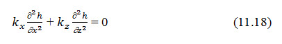
When the soil is isotropic i.e. kx = ky = kz, the preceding continuity equation for two-dimensional flow simplifies to:
Key words: Seepage, Flow net, Drainage
References
Harr, M. E. (1962). Ground Water and Seepage, McGraw-Hill, New York
Suggested Readings
Garg, S. K. (2011). Irrigation Engineering and Hydraulic Structures. Twenty Fourth Revised Edition. pp.811-814
Murthy, V.V.N. and Jha. M. K. 2011. Land and Water Management Engineering. Kalyani publication.
Last modified: Monday, 3 February 2014, 10:04 AM