Site pages
Current course
Participants
General
Module 1: Fundamentals of Reservoir and Farm Ponds
Module 2: Basic Design Aspect of Reservoir and Far...
Module 3: Seepage and Stability Analysis of Reserv...
Module 4: Construction of Reservoir and Farm Ponds
Module 5: Economic Analysis of Farm Pond and Reser...
Module 6: Miscellaneous Aspects on Reservoir and F...
Lesson 15 Seepage Analysis I
15.1 Introduction
Many soils are formed in horizontal layers as a result of sedimentation through water. Because of seasonal variations such deposits tend to be horizontally layered and this results in different permeability’s in the horizontal and vertical directions.
15.2 Permeability of Layered Deposits
Consider the horizontally layered deposit (Fig. 15.1), which consists of pairs of layers the first of which has a permeability of k1 and a thickness of d1overlaying a second which has permeability k2and thickness d2.
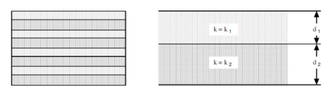
Fig. 15.1. Layered soil. (Source: https://www.u-cursos.cl/ingenieria/2008/1/CI44A/2/material_docente/objeto/175689.)
First consider horizontal flow in the system and suppose that a head difference of ∆h exists between the left and right hand sides (Fig. 15.2).
It then follows from Darcy’s law that,
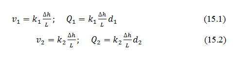
It, therefore, follows:
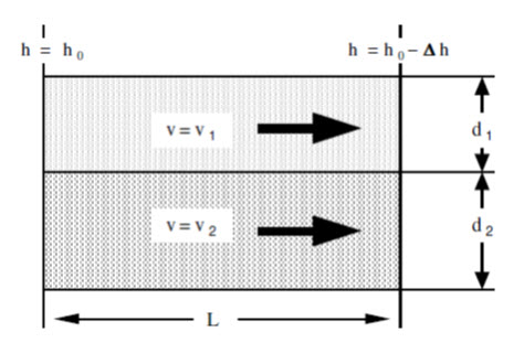
Fig. 15.2. Horizontal flow through layered soil.
(Source: https://www.u-cursos.cl/ingenieria/2008/1/CI44A/2/material_docente/objeto/175689.)
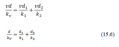
Next consider vertical flow through the system, shown in fig.15.3. Suppose that the superficial velocity in each of the layers is v and that the head loss in layer 1 is ∆h1, while the head loss in layer 2 is ∆h2.
In layer 1:
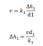
Similarly in layer 2,

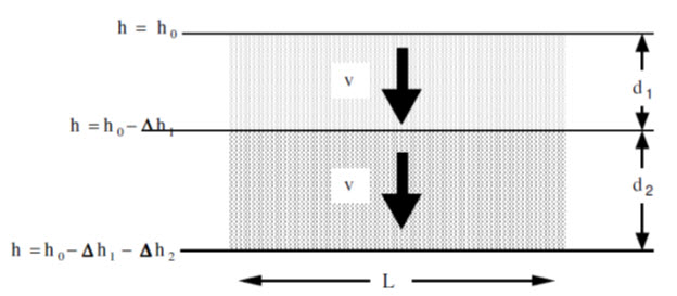
Fig. 15.3. Vertical flow through layered soil.
(Source: https://www.u-cursos.cl/ingenieria/2008/1/CI44A/2/material_docente/objeto/175689.)
The total head loss across the system will be ∆h=∆h1+∆h2 and the hydraulic gradient will be given by,
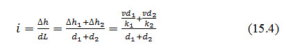
For vertical flow Darcy's law gives,
Total head loss is, ∆h =, we can write,
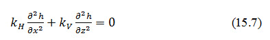
15.3 Flow Nets for Soil with Anisotropic Permeability
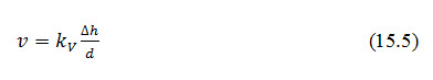
Flow in a plane in an anisotropic material having a horizontal permeability kH and a vertical permeability, kv is governed by the equation:
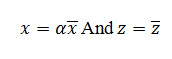
The solution of this equation can be reduced to that of flow in an isotropic material by the following simple device. Introduce new variables defined as follows:
Dividing the equation by, the seepage equation then becomes
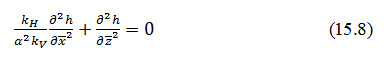
Thus by choosing:
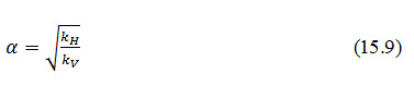
It is found that the equation governing flow in an anisotropic soil reduces to that for an isotropic soil, viz.:
and so the flow in anisotropic soil can be analyzed using the same methods (including sketching flow nets) that are used for analyzing isotropic soils.
15.4 Seepage in Anisotropic Soil: Example
Suppose we wish to calculate the flow under the dam as shown in Fig. 15.4:
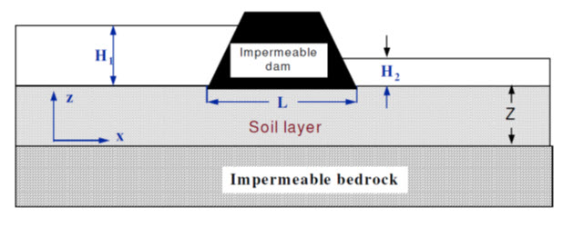
Fig. 15.4. Dam on a permeable soil layer above impermeable rock (natural scale).
(Source: https://www.u-cursos.cl/ingenieria/2008/1/CI44A/2/material_docente/objeto/175689.)
For the soil shown in Fig.15.4 it is found that kH= 4kV. Therefore,
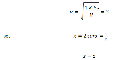
Transformed co-ordinates of a dam on a permeable layer over an impermeable rock and its flow net are shown in Fig.15.5and Fig.15.6, respectively. A rigorous proof of this result will not be given here, but it can be demonstrated to work for purely horizontal flow as:
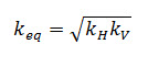
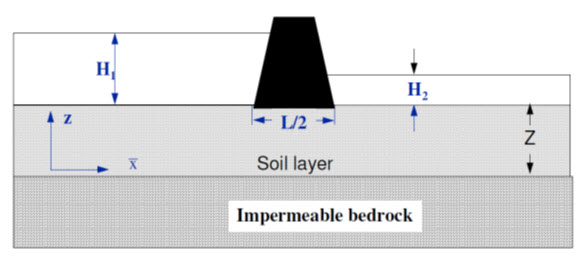
Fig. 15.5. Dam on a permeable layer over impermeable rock (Transformed scale).
(Source: https://www.u-cursos.cl/ingenieria/2008/1/CI44A/2/material_docente/objeto/175689.)
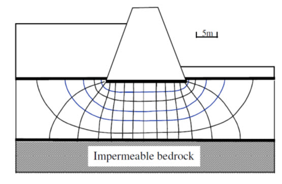
Fig. 15.6. Flow net for transformed geometry.
(Source: https://www.u-cursos.cl/ingenieria/2008/1/CI44A/2/material_docente/objeto/175689.)
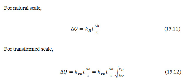
Figure 15.7 shows horizontal flow through anisotropic soil in natural and transformed scale.
Fig. 15.7. Horizontal flow through anisotropic soil.
(Source: https://www.u-cursos.cl/ingenieria/2008/1/CI44A/2/material_docente/objeto/175689.)
Key words: Anisotropic soil, Flow net, Seepage
References
Suresh, R. (2002). Soil and Water Conservation Engineering. Fourth Edition. Standard Publishers.
https://www.ucursos.cl/ingenieria/2008/1/CI44A/2/material_docente/objeto/175689.)
Suggested Readings
Last modified: Monday, 3 February 2014, 11:29 AM