Site pages
Current course
Participants
General
Module 1: Fundamentals of Reservoir and Farm Ponds
Module 2: Basic Design Aspect of Reservoir and Far...
Module 3: Seepage and Stability Analysis of Reserv...
Module 4: Construction of Reservoir and Farm Ponds
Module 5: Economic Analysis of Farm Pond and Reser...
Module 6: Miscellaneous Aspects on Reservoir and F...
Lesson 19 Control of Seepage Using Drainage System
The water seeping through the body of the earthen dam or through the foundation of the earthen dam may prove harmful to the stability of the dam by causing softening and sloughing of the slopes due to development of pore pressures. It may also cause piping either through the body or through the foundation, and thus resulting in the failure of the dam.
19.1 Seepage Control through Embankments
Drainage filters called drains are generally provided in the form of (a) rock toe (b) horizontal blanket (c) chimney drain, etc., in order to control the seepage water. The provision of such filters reduces the pore pressure in the downstream portion of the dam and thus increases the stability of the dam, permitting steep slopes and thus affecting economy in construction. It also checks piping by migration of particles. These drain, consists of graded coarse material in which the seepage is collected and moved to a point where it can be safely discharged. In order to prevent movement of the fine material from the dam into the drain, the drain or filter material is graded from relatively fine on the periphery of the drain to course near the centre. A multi layered filter, generally called inverted filter or reverse filter is provided as per the criteria suggested by Terzaghi for the design of such filters. The various kinds of drains, which are commonly used are shown and described below.
19.1.1 Rock Toe or Toe Filter
The rock toe consists of stones of size usually varying from 15 to 20 cm (Fig. 19.1). A toe filter (graded in layers) is provided as a transition zone, between the homogeneous embankment fill and rock toe. Toe filter generally consists of three layers of fine sand, coarse sand, and gravel; as per the filter criteria requirements. The height of the rock toe is generally kept between 25 to 35% of reservoir head. The top of the rock toe must be sufficiently higher than the tail water depth, so as to prevent the wave action of the tail water.
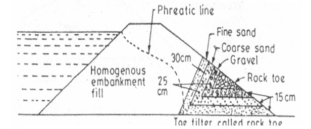
Fig. 19.1. Rock Toe.
(Source: Garg, 2011)
19.1.2 Horizontal Blanket or Horizontal Filter
The horizontal filter extends from the toe (d/s end) of the dam, inwards, up to a distance varying from 25 to 100% of the distance of the toe from the centre line of the dam. Generally a length equal to three times the heights of the dam is sufficient. The blanket should be properly designed as per the filter criteria, and should be sufficiently previous to drain effectively (Fig. 19.2 and 19.3).

Fig. 19.2. Horizontal filter.
(Source: Garg, 2011)
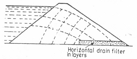
Fig. 19.3. Inefficient horizontal drain in stratified embankments.
(Source: Garg, 2011)
19.1.3 Chimney Drain
The horizontal filter not only helps in bringing the phreatic line down in the body of the dam but also provides drainage of the foundation and helps in rapid consolidation. But the horizontal filter tries to make the soil more previous in the horizontal direction and thus causes stratification. When large scale stratification occurs, such a filter becomes inefficient (Fig.19.3). In such a possible case, a vertical filter is placed along with the horizontal filter, so as to intercept the seeping water effectively (Fig.19.4). Such an arrangement is termed as chimney drain. Sometimes a horizontal filter is combined and placed along with a rock toe (Fig.19.5).

Fig. 19.4. Chimney drain in stratified embankments.
(Source: Garg, 2011)
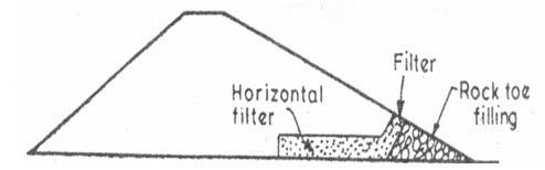
Fig. 19.5. Horizontal filter combined with rock toe.
(Source: Garg, 2011)
19.2 Seepage Control through Foundations
The amount of water entering the pervious foundations can be controlled by adopting the following measures:
19.2.1 Impervious Cut-offs
Vertical impervious cut-offs made of concrete or sheet piles may be provided at the upstream end (i.e.at heel) of the earthen dam (Fig. 19.6). These cutoffs should, generally extend through the entire depth of the pervious foundation, so as to achieve effective control on the seeping water.

Fig. 19.6. Impervious cutoff.
(Source: Garg, 2011)
When the depth of the pervious foundation strata is very large, a cut-off, up to a lesser depth, called a partial cutoff may be provided. Such a cut-off reduces the seepage discharge by a smaller amount. So much so, that a 50% depth reduces the discharge by 65% or so.
19.2.2 Relief Wells and Drain Trenches
When large scale seepage takes place through the pervious foundation, overlain by a thin less pervious layer, there is a possibility that the water may boil up near the toe of the dam (Fig 19.7).
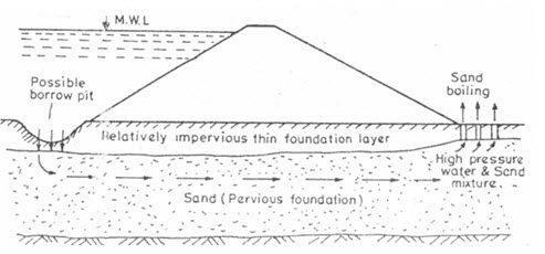
Fig. 19.7. Sand boiling phenomenon.
(Source: Garg, 2011)
Such a possibility can be controlled by constructing relief wells or drain trenches through the upper impervious layer (Fig. 19.8 and 19.9).
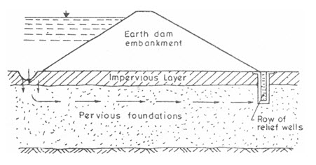
Fig. 19.8. Sand boiling phenomenon.
(Source: Garg, 2011)
So as to permit escape of seeping water, the possibility of sand boiling may also be controlled by providing d/s berms beyond the toe of the dam (Fig. 19.10). The weight of the overlying material, in such a case, is sufficient to resist the upward pressure and thus preventing the possibility of sand boiling. The provision of such berms also protects the d/s toe from possible sloughing due to seepage.
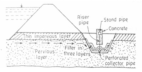
Fig. 19.9. Enlarge view of drain trench.
(Source: Garg, 2011)

Fig. 19.10. Provision of d/s berm.
(Source: Garg, 2011)
19.3 Design Criteria of Filters
The drainage filters must be designed in such a way that neither the embankment nor the foundation material can penetrate and clog the filters. The permeability or size of filter material should also be sufficient to carry the anticipated flow with an ample margin of safety. A rational approach to the design of filters has been provided by Terzaghi. According to him, the following filter criteria should be satisfied.
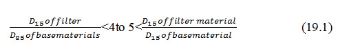
The embankment soil or the foundation soil surrounding the filter is known as base material. When the ratio of D15 of filter to D85 of base material does not exceed 4 to 5, base material is prevented from passing through the pores of the filter. Similarly, when the ratio of D15 of filter to D15 of base material is more than 5(between 5to 40), the seepage forces within the filter are controlled up to permissible small magnitudes.
Multilayered filters(generally 3 layers) consisting of materials of increasing permeability’s from the bottom to top are, many a times, provided and are known as inverted filters. These filters are costly and should be avoided where possible. The minimum total thickness of filter is 1 m. However, if sufficient quantities of filter material are available at reasonable costs, thicker layers of filter may be provided. The thicker the layer, there is greater permissible deviation from the filter requirements.
Keywords: Seepage, Drainage, Filter, Foundation
References
Anonymous (2011). Filters for Embankment Dams: Best Practices for Design and Construction. Federal Emergency Management Agency, US Department of Homeland Security.
Garg, S. K. (2011). Irrigation Engineering and Hydraulic Structures. Twenty Fourth Revised Edition, pp.811-814.
Suresh, R. (2002). Soil and Water Conservation Engineering. Fourth Edition, pp. 560-562.
Suggested Readings
Murthy, V.V.N. and Jha. M. K. (2011). Land and Water Management Engineering, Kalyani Publication.
Tang, K. D., Wang, G. J. and Xu, Z.S. (2012) The Application of drainage filters in earth dam reinforcement. Applied Mechanics and Materials, 170-173: 2162-2165.
Last modified: Tuesday, 4 February 2014, 5:47 AM