Site pages
Current course
Participants
General
Module 1: Fundamentals of Reservoir and Farm Ponds
Module 2: Basic Design Aspect of Reservoir and Far...
Module 3: Seepage and Stability Analysis of Reserv...
Module 4: Construction of Reservoir and Farm Ponds
Module 5: Economic Analysis of Farm Pond and Reser...
Module 6: Miscellaneous Aspects on Reservoir and F...
Lesson 21 Stability Analysis II
21.1 Slices Method of Stability Analysis
The slices method stability analysis was introduced by Fellinius. In this analysis, the earth forces are considered having a direction that makes an angle with the vertical sides of the slices, as well as with the water forces acting on the sides of the slices. For example, in the case of analysis of a sloping core dam, there is appreciable difference in shear strength between the shell and core materials. The factor of safety computed neglecting earth forces on the sides of the slices is lower than that computed considering earth forces, and an unnecessarily conservative design result. The variation, considering earth forces on the sides of the slices, is necessary when it is desired to analyze the stress conditions point by point along the failure surface. An improper distribution of stresses results when the earth forces on the vertical sides of the slices are neglected. Its alternative is the assumption that lateral earth forces exist but their direction is parallel to the base of the slice.
The first step is to divide the sliding mass into a number of vertical slices. The sliding surface may be a circular arc or a combination of areas and straight lines. The number of slices chosen usually is about 8 to 10. This number is consistent with general accuracy of the method. Width of each slice need not to be uniform and the widths are adjusted so that the entire base of each slice is located on a single material.
The forces acting on a typical slice (Fig. 21.1) and consist of WT= total weight of the slice, EL, ER= earth forces on left and right hand vertical faces, respectively, UL, UR,UB= water forces on left and right hand vertical faces and bottom of slice, and P=resultant earth force on base of slice
The water forces are determined from water pressure diagrams on the sides and base of the slice determined from static water conditions if no seepage occurs or from flow nets if seepage occurs. The directions of water pressure are perpendicular to the surfaces on which they act. Sometimes a lateral force may be used, which is a combination of an earth force and a water force on the side of the slice. Pressures generated in the pore water by consolidation and shearing in the embankment are taken into consideration in various ways depending upon the method used for expressing shear strength.
The resultant force on the base of the slice P can be represented by a component N normal to the base of the slice and a component SD tangential to the base of the slice. The resultant force of N and N tanϕD is Pf. The tangential component can be separated into two parts, namely, N tanfD and cD (Fig.21.1).
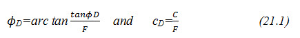
Where, ØD=developed friction angle, CD = developed cohesion, c = cohesion, and F= factor of safety
Different values of factor of safety (F) may be used in the above expressions; however, it is preferred to use the same for both.
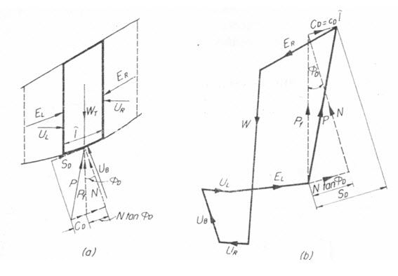
Fig. 21.1. Force polygon for a slice, (a) Slice, and (b) Force polygon.
(Source: Davis, 1969)
The polygon for the forces acting on the typical slice of Fig.21.1a is shown in Fig.21.1b. The magnitude and direction of the forces WT, UB, UL, and UR are determined from the geometry of the slice, the unit weight of the soil, and reservoir and ground water conditions. The direction of each of the forces EL and ER may be assumed as midway between the directions of the face and the failure surface of the vertical plane on which the force E acts. The values of the soil parameters c and ϕ are known from soil testing.
The solution for the factor of safety is made by trial and error. The analysis is started at the topmost slice where only one E force is acting. A trial factor of safety is assumed and the force polygon for the topmost slice is constructed. On the basis of the assumed factor of safety, the force CD can be computed. The magnitudes of EL, N and N tanϕD are unknown, but the directions of EL and that of the resultant force N tanϕD are known, and this permits the closure of the force polygon. Having determined EL for slice 1, ER for slice 2, which is the reaction of EL on slice1, is also determined. The force polygon slice 2 and other remaining slices is then completed in a similar manner as per slice 1. For the last slice as similar to the first, only one E force exists and its force polygon is determined. If on using the E force as obtained from the previous slice, the force polygon for the last slice does not close, a new trial is required using a different value of factor of safety. When the proper value of factor of safety has been assumed, the force polygon for the final slice will close.
21.2 Swedish Slip Circle Method
An earth embankment usually fails, because of the sliding of a large soil mass along a curved surface. It has been established by actual investigation of slides of railway embankment in Sweden that the surface of slip is usually close to cylindrical, i.e. an arc of a circle in cross-section. The method which is described here and is generally used for examining the stability of slopes of an earthen embankment is called the Swedish slip circle method or the slices method. The method thus assumes the condition of plane strain with failure along a cylindrical.
The location of the center of the possible failure arc is assumed. The earth mass is divided into a number of vertical segments called slices. These verticals are usually equally spaced, though it is not necessary to do so. Depending upon the accuracy desired, six to twelve slices are generally sufficient.
Let O be the center and r be the radius of the possible slip surface (Fig. 21.2). Let the total arc AB be divided into slices of equal width say b meters each. The width of the last slice will be something different say let it be m×b meters.
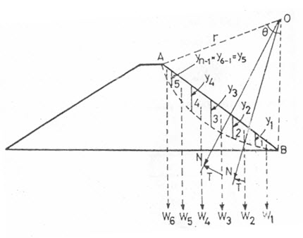
Fig. 21.2. Swedish slip circle method. (Source: Garg, 2011)
Let these slice be numbered as 1,2,3,4......... and let the weight of these slices be w1, w2, w3, w4……..
The forces between these slices are neglected and each slice is assumed to act independently as a vertical column of soil of unit thickness and width b. The weight W of each slice is assumed to act at its center. The weight W of each slice can be resolved into two components; say a normal component (N) and a tangential component (T) such that
N=W cos α
T=W sin α (21.2)
Where, α= angle which the slope makes with the horizontal.
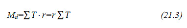
The normal component (N) will pass through the center of rotation (O) and hence does not create any moment on the slice. However, the tangential component (T) causes a distributing moment equal to (T ×r), where r is the radius of the slip circle. The tangential components of a few slices may create resisting moments; in that case T is considered as negative. The total distributing moment (Md) will be equal to the algebraic sum of all the individual tangential moments, i.e.
The resisting moment is supplied by the development of shearing resistances of the soil along the accrual surface AB. The magnitude of shear strength developed in each slice will depend upon the normal component (N) of that slice. Its magnitude will be
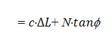
Where, c = unit cohesion, = curved length of the slice, and = angle of internal friction of soil.
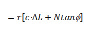
This shear resistance is acting at a distance r from O and will provide a resisting moment
The total resisting moment over the entire arc AB
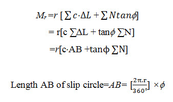
Where, = angle in degrees, formed by the arc AB at centre O.
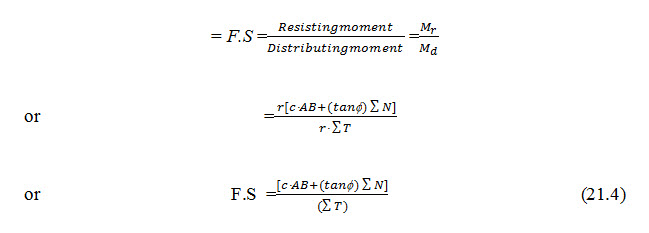
Hence, the factor of safety (FS) against sliding is
Equation (21.1) can be worked out by working out and separately. This evolution of and can be simplified as explained below.
Ify1, y2, y3... are the vertical extreme ordinates (boundary ordinates) of the slices 1, 2, 3... then respective weights can be written as
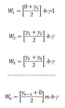
Where, g= unit weight of soil and unit width of the slice, and n = total number of slices.
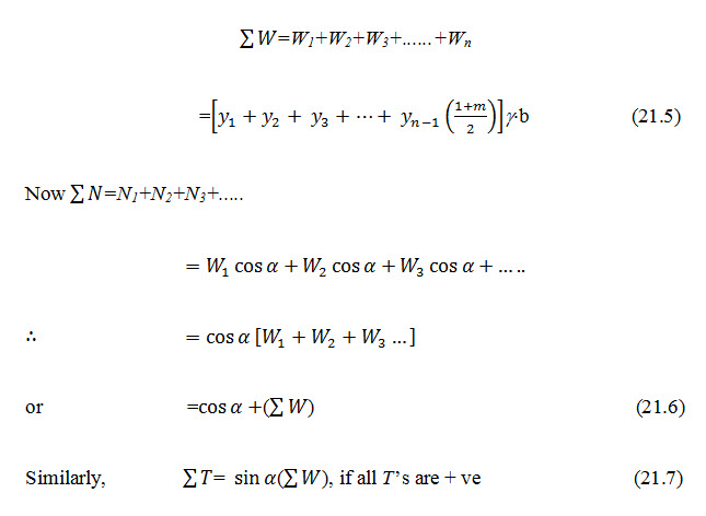
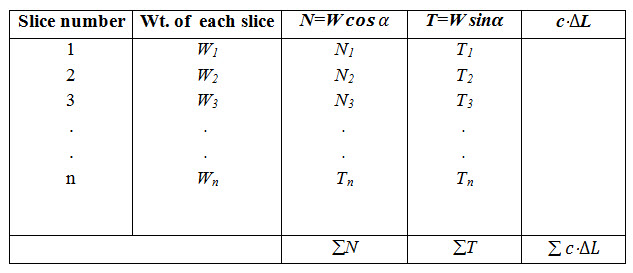
The area of N diagram will represent and that of T diagram will represent .As a general case, the value of and can be worked out in a tabular form (Table 21.1).The F.S. is then calculated as
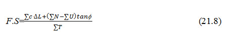
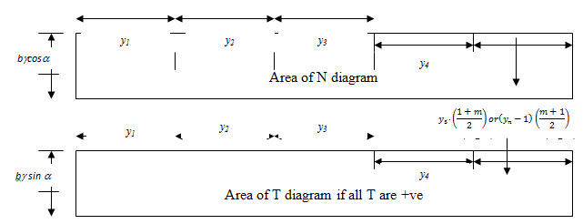
Fig. 21.3. Area of N and T diagram. (Source: Garg, 2011)
Table 21.1. Weight of slices, N and T Components (Source: Garg, 2011)
21.3 Location of the Centre of the Critical Slip Circle
In order to find out the worst case, numerous slip circles should be assumed and factor of safety (F.S) calculated for each circle, as explained earlier. The minimum factor of safety will be obtained for the critical slip circle. In order to reduce the number of trails, Fellenius has suggested a method of drawing a line (PQ), representing the locus of the critical slip circle.
The determination of line PQ for the d/s and u/s slopes of an embankment is shown in Fig. 21.4(a) and Fig. 21.4(b), respectively. The point Q is determined in such a way that its coordinates are from the toe (Fig. 21.4 a). The point P is obtained with the help of directional angles α1and α2 for various slopes (Table 21.2).
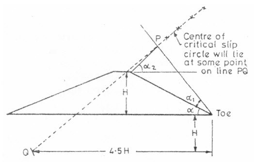
Fig. 21.4 (a). Locus of critical circle for d/s slope
(Source: Garg, 2011)
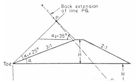
Fig. 21.4 (b). Locus of critical circle for u/s slope.
(Source: Garg, 2011)
Table 21.2. Directional angles against embankment slopes (Source: Garg, 2011)
|
Slope |
Directional angles |
|
|
α1 in degrees |
α2 in degrees |
|
|
1:1 2:1 3:1 4:1 5:1 |
27.5 25 25 25 25 |
37 35 35 35 35 |
After determining the locus of the critical slip circle, it can be drawn, keeping in view the following few points:
a) Except for very small values off, the critical arc passes through the toe of the slope.
b) If a hard stratum exists at shallow depth under the dam, the critical arc cannot cross this stratum, but can only be tangential to it.
c) For very small values of f(0 to 15o), the critical arc passes below the toe of the slope if the inclination of the slope is less than 53 (which is generally the case). The center of the critical arc in such a case is likely to fall on a vertical line drawn through the center of the slope (Fig. 21.5).
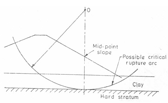
Fig. 21.5. Center of critical arc.
(Source: Garg, 2011)
Keywords: Stability analysis, Slices method, Swedish slip, Critical slip circle
References
Davis, C.K. (1969). Handbook of Applied Hydraulics. Second Edition. McGraw-Hill, New York.
Garg, S. K. (2011). Irrigation Engineering and Hydraulic Structures. Khanna Publication. Twenty fourth revised edition.
Suggested Readings
Suresh, R. (2002). Soil and Water Conservation Engineering. Fourth Edition.
Fellinius, W. (1936).Calculation of the stability of earth dams, Trans. 2nd Congress on Large Dams, Washington D C, 4, pp 445-65.
ftp://ftp.pwut.ac.ir/Exercises/ghorbanbeigi/tennessee/soil/361-sl14.pdf
Last modified: Tuesday, 4 February 2014, 9:31 AM