Site pages
Current course
Participants
General
Module 1: Fundamentals of Reservoir and Farm Ponds
Module 2: Basic Design Aspect of Reservoir and Far...
Module 3: Seepage and Stability Analysis of Reserv...
Module 4: Construction of Reservoir and Farm Ponds
Module 5: Economic Analysis of Farm Pond and Reser...
Module 6: Miscellaneous Aspects on Reservoir and F...
Lesson 24 Slope Protection
24.1 General Considerations
The slopes of earth embankments must be protected against erosion by wave action, rain wash, frost and wind action. Protection cannot economically be provided against the erosion which would occur if the dam were overtopped. A major cause of earth dam failures has been overtopping, therefore, care must be exercised that freeboard and spillway capacity are ample to prevent it.
24.2 Freeboard
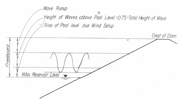
Freeboard is the vertical distance between the maximum water surface of the spillway design flood and the crest of the dam. The vertical distance should be ample to prevent overtopping of the dam due to wind setup (rise in water level at dam due to wind blowing toward dam). The height of waves above pool level, and run-up of waves on the face of the dam is illustrated in Fig. 24.1.
Wind setup may be computed by the Zuider Zee formula:

Where, S = setup above normal pool level, ft; V = wind velocity, mph; F = fetch, miles; D = average depth of water, ft; and A= angle between direction of waves and normal to face of dam.
The height of waves may be computed using the Molitor-Stevenson equations given below.

Fig. 24.1. Freeboard.
For a fetch less than 200 miles,
![]()
Where hw= height of wave from trough to crest, ft. Three quarters of the height of wave is considered to be above the pool level.
The run-up of waves on the face of the dam may be computed by the formula

This formula does not contain a term expressing the roughness of the face and so is approximate.
Fetch is the distance from the dam to the opposite shore. Generally the straight line distance is used. Where slight bends in the measured line will lengthen the fetch, however, such bends should be incorporated according to judgment.
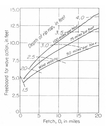
The relationship between freeboard for wave action (omitting setup) and fetch for wind velocities of 50, 75 and 100 mph is shown graphically in Fig. 24.2. The freeboard for wave action plus the freeboard for setup almost always be greater than 5 ft. It is thus greater than the usual depth of frost penetration. If the depth of frost penetration is greater than the above computed distance, the depth of frost penetration should be used for the freeboard distance.

Fig. 24.2. Relationship between fetch, freeboard for wave action, and thickness of dumped riprap for slope protection.
The types of slope protection used on earth dams and levees vary from sod to several feet of dumped riprap. The choice of slope protection for a particular slope depends upon the type of erosive action against which the slope is to be protected and the frequency of attack. The discussion below takes up the various types of slope protection, which may be considered for the upstream and downstream faces of dam’s levees.
24.3 Upstream Protection
The upstream slopes of dams are commonly protected with dumped riprap or its equivalent. The thickness of the riprap may vary from 1.5 to 5 ft, depending on the severity of wave action. Suggested values for thickness of riprap for various fetches and wind velocities are given in Fig. 24.2. The riprap should be founded on a filter designed. The thickness of the filter should be about 1 ft. The stone used for riprap should be hard and durable and be able to resist long exposure to weathering. Stone suitable for riprap generally should be able to pass the standard soundness tests used for concrete aggregate. However, occasionally rock which casehardens will not pass soundness tests and yet be satisfactory for riprap. Fifty percent of the stone by weight should have diameters about equal to the proposed thickness of riprap. The remaining 50 percent should be graded downward as quarry conditions permit for reasonable design of the underlying filter bed. The riprap should extend from the top of the dam to about 5 ft below the lowest normal pool level. To prevent raveling at the lower end, the riprap is usually abutted against a large stone embedded in the embankment. Also a berm is frequently located at the lower end of the riprap to assist in preventing raveling and to facilitate construction of the riprap. Where rock is expensive a layer of hand placed riprap about half the thickness of the dumped riprap may prove more economical, the cost of the additional labour required being compensated by the saving in quantity of rock used. Run-up of waves on the relatively smooth face of hand placed riprap is greater than on dumped rip-rap. Other alternatives, which may be considered where rock is expensive, are cast tetrahedron blocks of concrete, ceramic blocks or soil cement. Slope protection consisting of continuous concrete pavement has also been used occasionally.
From the observations it has been found that, the protection works of u/s slope, using concrete slab, are failed by about 36% cases, mainly because of non-providing of the filter below them.
24.4 Protection of Downstream Slope
The downstream face of an earth dam is usually protected with sod where the climate is suitable. In climates where sod cannot grow, a thin layer of stone or gravel riprap may be used. To develop a sod, 4 to 6 in. of topsoil is spread on the downstream face and the face seeded and strip-sodded. The grass or vine used for making the sod will depend on local conditions. Berms, which intercept the runoff, have at times been used on the face of the dam. Care must be exercised, however in designing and maintaining the berms to see that the water which they intercept is safely conducted away, otherwise, the berms may cause more difficulty than they prevent. Culverts are generally required at the intersection of the faces of the embankment with the abutments.
Where riprap is used on the downstream face, its thickness and permeability should be ample to conduct safely the rainwater flowing down the slope. The stability of such riprap against sloughing caused by the seepage force of the rain wash can be analyzed using various methods. Where the downstream slopes of earth dams are subject to tail water, they should be protected by riprap.
Both the riverside and landside slopes of levees are commonly protected with sod. Where river currents would cause erosion of the sod, as at the outside of bends, dumped riprap slope protection or its equivalent may be used. Other types of slope protection that have been used on levees include articulate concrete mats, asphalt pavement and willow mats.
Key words: Fetch, Freeboard, Riprap, Slope protection, Wave action
References
Garg, S. K. (2011). Irrigation Engineering and Hydraulic Structures. Khanna Publishers, Twenty Fourth Revised Edition. pp. 643-654.
Murthy, V. V. N. and Jha, M. K. (2011). Land and Water Management Engineering. Kalyani Publishers.
Stephen, T. (2010). Manual on Small Earth Dams: A Guide to Siting, Design and Construction. FAO Irrigation and Drainage Paper. FAO of the United Nations, Rome.
Panigrahi, B. (2011). Irrigation System Engineering. First Edition. New India Publishing Agency.
Suggested Readings
Suresh, R. (2002). Soil and Water Conservation Engineering. Standard Publishers.
Central Water and Power Commission (1960). Embankment Manual. Ministry of Irrigation and Drainage Power, New Delhi.
Creager, W. P. and Julian Hinds (1968). Engineering for Dams. Vol. I, II and III. Wiley Eastern, New Delhi.
Punmia, B. C., Pande, B. B. L., Jain, A. K., and Jain, A. K. (2009). Irrigation and Water Power Engineering. Laxmi Publication Pvt. Ltd., 964 pages.