Site pages
Current course
Participants
General
Module 1: Fundamentals of Reservoir and Farm Ponds
Module 2: Basic Design Aspect of Reservoir and Far...
Module 3: Seepage and Stability Analysis of Reserv...
Module 4: Construction of Reservoir and Farm Ponds
Module 5: Economic Analysis of Farm Pond and Reser...
Module 6: Miscellaneous Aspects on Reservoir and F...
Lesson 16 Seepage Analysis II
16.1 Stability Condition during Steady Seepage
Stability of the d/s slope of the dam must be examined under the occurrence of most critical condition when the reservoir is full and the seepage is taking place at full rate.
The seeping water below the phreatic line exerts a pore pressure on the soil mass which lies below the phreatic line. Hence, if the slices of the critical arc, happen to include this submerged soil (Fig. 16.1a.), the shear strength developed on those slices shall be correspondingly reduced. The net shear strength on such a slice shall be = cL + (N-U) tan f, where U is the pore pressure.
The factor of safety (F.S.) for the entire slip circle is then given by the equation (refer lesson 21).
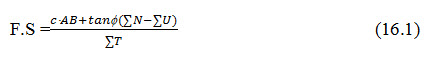
Where, ø= angle of internal friction, ΣU = total pore pressure on the slip circle, ΣN = total normal components on submerged density, and ΣT= total tangential components on saturated unit weight of soil.
The pore pressure at a point is represented by the piezometric head at that point.
The variation of the pore pressure along a failure arc is, therefore, obtained as explained below:
First of all, draw a flow net and thus determine the points of intersection, measure the vertical ordinate from that intersection to the level at which that particular equipotential line cuts the phreatic line. The pore pressures represented by the vertical heights so obtained are then plotted to a scale in a direction perpendicular to the sliding surface at the respective points of intersection. The pore pressure distribution is shown in Fig. 16.1 b.

(a)

Fig. 16.1. Pore pressure distribution.
(Source: Garg, 2011)
The area of this diagram can be measured by a planimeter. The area of this diagram can also be calculated by ordinate method as was done for N and T cases taking the unit weight of water as 9.81 kN/m3 (»10 kN/m3). Knowing åN, åU, åT, and F.S. can be calculated easily by using Eqn (16.1).
Approximate Method
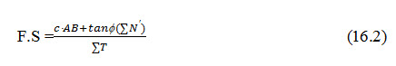
In the absence of a flow net, the normal components, which are responsible for the shear strength of the soil, can be calculated on the basis of submerged unit weight of soil. On the other hand, the values of tangential components (T), which are responsible for creating distributing moments, should be calculated on the basis of saturated unit weight of soil.
In such a case, the width of N rectangle which was taken as will become (Fig. 21.3)and the width of T rectangle will remain The new N diagram is adiagram assuming the entire soil to be submerged and can be called N diagram. Equation 16.1 can be written as
16.2 Stability of Upstream Slope during Sudden Drawdown
When the reservoir is full, the critical region is near the downstream face. If no drainage arrangement is made and the d/s slope is also steep, the phreatic line may intersect the d/s slope creating serious conditions there. This can be avoided by providing drainage filter or drainage toe, etc., or by broadening the base of the dam so that the head loss is great enough to bring the line of saturation beneath the d/s toe of the dam.
For the u/s slope, the critical condition can occur, when the reservoir is suddenly emptied. In such a case, the water level within the soil will remain as it was when the soil pores were full of water. The weight of this water within the soil now tends to slide the u/s slope along a circular arc.
The tangential component of the saturated soil lying over the arc, will create a distributing force; while the normal components minus the pore pressure shall supply the shear strength of the soil. High pore pressures shall be developed in this case and although a true solution can be obtained from the flow net and pressure net. An approximate solution can be easily obtained by considering the soil resting over the failure arc as saturated, for calculating T's; and as submerged for calculating N’s.
The factor of safety (F.S) is finally obtained as
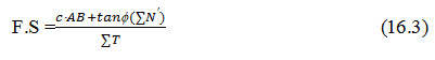
The maximum factor of safety obtained for the critical slip circle should be1.5, for safe designs.
Case I: Consideration of horizontal shear developed at base under the u/s slope of the dam
An approximate method for checking the stability of the u/s slope against sudden drawdown is presented here. It is based on the simple principle that a horizontal shear force (say Pu) is exerted by the saturated soil (i.e.by the soil as well as by water contained within the soil). The resistance to this shear force (Ru) is provided by the shear resistance developed at the base of the soil mass, contained within the u/s triangular shoulder, GMN. (Fig. 16.2)
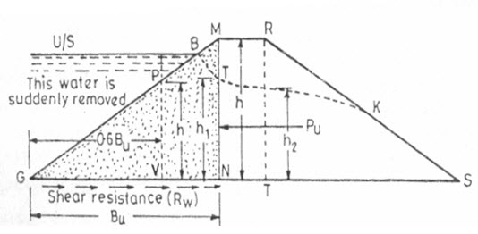
Fig. 16.2. Shear resistance development.
(Source: Garg, 2011)
Considering a unit length of the dam, the horizontal shear force Pu is given by the equation
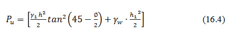
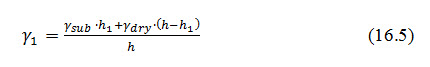
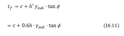
Where, weighted density at the centre of triangular upstream shoulder and is given by
Shear resistance of u/s slope portion of the dam developed at base GN is given by
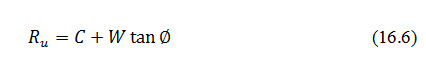
Where, W= weight of the u/s triangular shoulder of dam, and C=total cohesive force developed at base, GN.
If c is the unit cohesion of the dam soil, then where,= length GN.
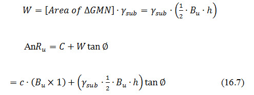
The triangular profile of the u/s slope portion of dam has an area GBTN as the submerged soil (soil below the seepage line) and an area equal to BMT as dry area. The correct weight W will be equal to. These areas can be measured by a plainmeter. If the measuring of the areas is to be avoided, the entire area may be taken as submerged. By doing so, the weight W will be slightly reduced, and thus or Ru or F.S. will be slightly reduced. Hence the results obtained will be on a safer side.
In such a case,
Now Pu and Ru are known, the factor of safety against sliding can be easily calculated, using
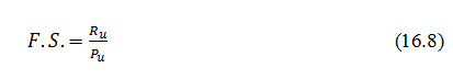
It should be more than 1.5.
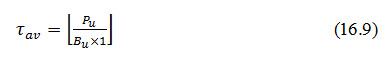
The factor of safety calculated above is with respect to average shear (av), which will be equal to
It has been found by photo-elastic studies that the maximum intensity of shear stress occurs at a distance 0.6 Bu from the heel (i.e.0.4Bu from the shoulder) and is equal to 1.4 times the average shear intensity.
Maximum shear stress induced
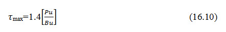
Which is developed at the point V (Fig. 16.2) such that GV=0.6 Bu.
The unit shearing resistance developed at this point V is given by
F.S at the point of the maximum shear
It should be more than 1.
Case II: Considerations of horizontal shear developed at base under the d/s slope of the dam
The stability of the d/s slope under steady seepage is generally tested with Swedish slip circle method. However, the F.S against the horizontal shear forces can be evaluated on the same principles as was done for the u/s slope in the previous paragraphs.
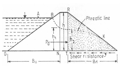
Fig. 16.3. Shear resistance development.
(Source: Garg, 2011)
With reference to Fig. 16.3, the horizontal shear force Pd, in this case, is given by
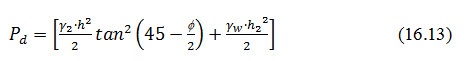
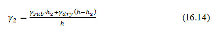
Where = weighted density at the centre of the triangular shoulder downstream, given by
Shear resistance Rd of d/s slope portion of dam, developed at base is given by
![]()
Where, W= weight of the d/s slope portion of dam, C=c× (Bd×1), where c is the unit cohesion.
The triangular profile of the d/s slope portion of dam (Fig. 16.3) has an area say A1 of dry soil above the seepage line and the area of submerged soil say A2 below the seepage lines. These areas can be measured by a planimeter and then,
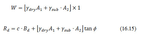
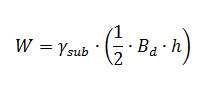
If the measuring of the areas is to be avoided, the entire weight W may be calculated on the basis of submerged soil, as it will be on a still safer side. In that case,
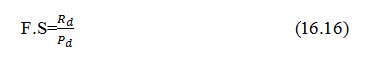
Knowing Pd and Rd, the factor of safety against shear can be easily determined as
The factor of safety at the point of maximum shear can also be determined in the same manner as was explained for the u/s slope portion.
Keywords: Stability, Shear resistance, Shear stress, Factor of safety
References:
Garg, S. K. (2011). Irrigation Engineering and Hydraulic Structures. Twenty fourth Revised Edition. pp. 769-803.
Suggested Readings:
Suresh, R. (2002). Soil and Water Conservation Engineering. Standard Publishers.
Murthy, V. V. N. and Jha, M. K. 2011. Land and Water Management Engineering. Kalyani Publishers.
Last modified: Tuesday, 4 February 2014, 4:55 AM