Site pages
Current course
Participants
General
MODULE 1. Analysis of Statically Determinate Beams
MODULE 2. Analysis of Statically Indeterminate Beams
MODULE 3. Columns and Struts
MODULE 4. Riveted and Welded Connections
MODULE 5. Stability Analysis of Gravity Dams
Keywords
LESSON 8. Force Method: Method of Consistent Deformation
8.1 Compatibility and Principle of Superposition
Displacement compatibility and principle of superpositon play an important role in the analysis of indeterminate structures.
8.1.1 Displacement compatibility
It is the condition which ensures the integrability or continuity of different members or components of a loaded structure while being deformed.
Example 1
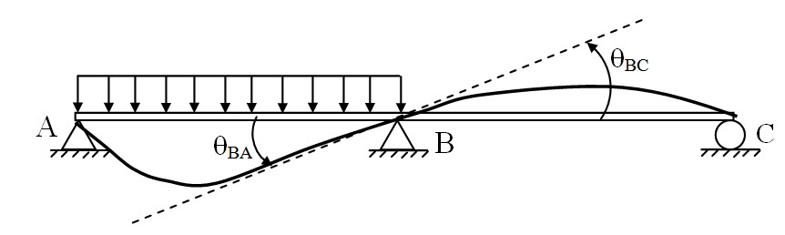
Fig. 8.1.
For the continuous beam shown in Figure 8.1, displacement compatibility conditions at B are,
δB = 0 and |θBA| = |θBC|
The second condition implies that the relative rotation at B is zero.
Example 2
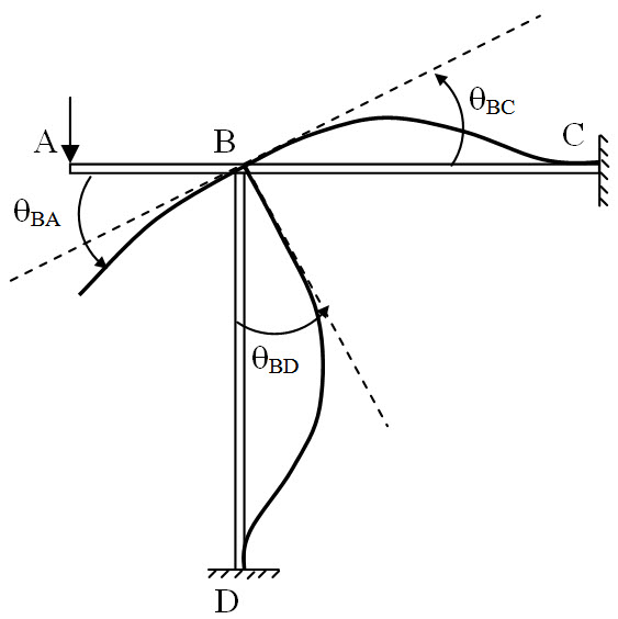
Fig. 8.2.
For the rigid frame shown in Figure 8.2, displacement compatibility conditions at B are,
θBA = θBC = θBD
8.1.2 Principle of Superposition
For a linear elastic structure, the deflection caused by two or more loads acting simultaneously is the sum of deflections caused by each load separately. For instance, suppose d be the deflection at mid-span of a simply supported beam subjected to three concentrated load P1, P2 and P3 (Figure 8.3a). If δ1, δ2, and δ3 are the deflection at mid-span respectively due to P1, P2, and P3 when they act separately, principle of superposition states,
δ = δ1+ δ2 + δ3
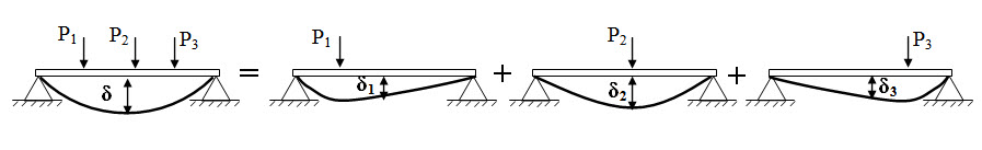
Fig. 8.3a.
For a linear elastic structure, load, P and deflection, δ , are related through stiffness, K, as P = Kδ. If δ1 and δ2 are the deflection due to P1 and P2 respectively, linearity implies, P1/P2 = δ1/δ2 .
8.2 General Procedure
Consider a propped cantilever beam subjected to a concentrated load at its mid-span as shown in Figure 8.4. It is an indeterminate structure with degree of static indeterminacy one.
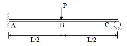
Fig. 8.4.
The steps involved in method of consistent deformation are as follows,
Step 1: Determine the Degree of Static Indeterminacy
The static indeterminacy of the propped cantilever beam is one.
Step 2: Redundant Force/Moment
A number of releases equal to the degree of indeterminacy is introduced. Each release is made by removing an external or an internal force/moment. This force/moment is called redundant force/moment. Redundant forces/moment should be chosen such that the remaining structure is stable and statically determinate.
For the given propped cantilever beam, the basic determinate structure may be obtained by removing the prop at C (Figure 8.5). Here vertical reaction Cy is the redundant force. The basic determinate structure becomes a cantilever beam with concentrated load at mid-span
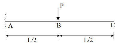
Fig. 8.5.
Alternatively moment constraint at A may also be taken as Redundant. This is explained in sub-section 1.2.1.
Step 3: Solution of Basis Determinate Structure
Calculate the magnitude of the displacement at the released end of the basic determinate structure. Any analysis procedure for determinate structure as discussed in Module I may be followed.
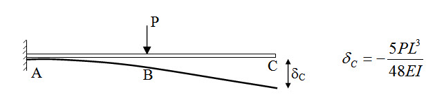
Fig. 8.6.
Here determine vertical displacement at C.
Step 4: Deflection due to Unknown Redundant Force/Moment
Remove all external loads on the basic determinate structure and apply an unknown value of redundant force/moment at the release end. Determine corresponding displacement at the release end in terms of the unknown value of redundant force/moment.
In this case apply vertical force at C and determine δC (Figure 8.7).
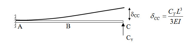
Fig. 8.7.
Step 5: Apply Compatibility Condition at the Release End
Apply displacement compatibility condition at the release end.
In this case vertical displacement at C is zero. Therefore,
\[{\delta _C}+{\delta _{CC}}=0\Rightarrow-{{5P{L^3}}\over {48EI}}+{{{C_Y}{L^3}}\over {3EI}}=0\Rightarrow{C_Y}={{5P}\over{16}}\]
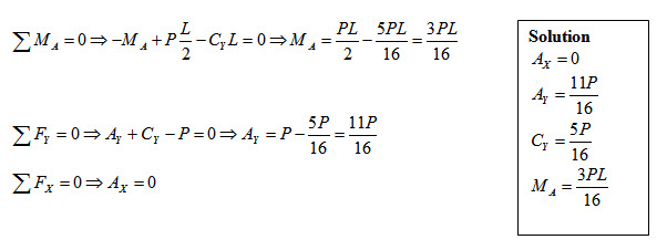
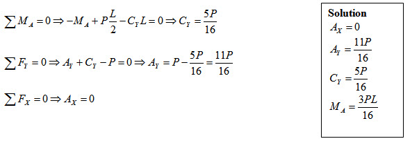
Step 6: Solve for Other Unknown
Once the redundant force/moment is determined, other support reaction may be found by using equilibrium equations.
8.2.1 Alternative Solution with Different Redundant Force/Moment
Step 1:
Degree of Static Indeterminacy is one.
Step 2:
Moment constraint at A is taken as redundant. The basic determinate structure becomes a simply supported beam with concentrated load at mid-span (Figure 8.8).
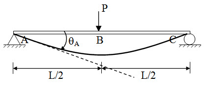
Fig. 8.8.
Step 3:
\[{\theta _A}={{P{L^2}} \over {16EI}}\]
Step 4:
Apply moment MA at A and calculate slope θAA.
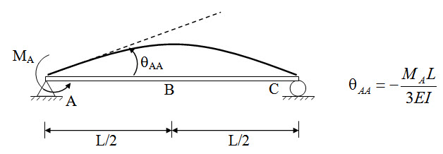
Fig. 8.9.
Step 5:
End A in the original structure is fixed and therefore slope at A is zero.
\[{\theta _A} + {\theta _{AA}}=0 \Rightarrow {{P{L^2}} \over {16EI}}-{{{M_A}L} \over {3EI}}=0 \Rightarrow {M_A}={{3PL} \over {16}}\]
Step 6:
8.3 Maxwell-Betti Reciprocal Theorem
Consider two points 1 and 2 in a simply supported beam as shown in Figure 8.10. The beam is separately subjected to two system of forces P1 and P2 at point 1 and 2 respectively. Let d12 be the deflection at point 2 due to P1 acting at point 1 (Figure 8.10a) and d21 be the deflection at point 1 due to P2 acting at point 2 Figure 8.10b).
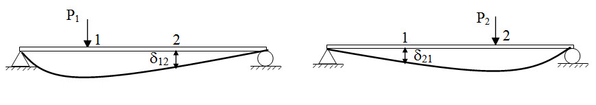
Fig.8.10 (a) Fig.8.10 (b)
The Reciprocal theorem states, the work done by the first system of forces acting through the displacement of second system is the same as the work done by the second system of forces acting through the displacement of first system. Therefore,
\[{P_1}\times{\delta _{21}}={P_2}\times {\delta _{12}}\]
The reciprocal theorem is also valid for moment-rotation system. For instance, for the system shown in Figure 8.11, the reciprocal theorem gives,
\[{M_1} \times {\theta _{21}}={M_2} \times {\theta _{12}}\]
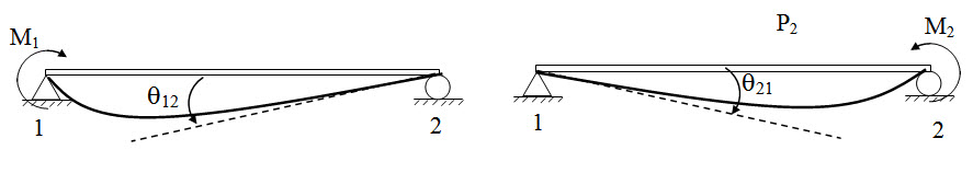
Fig. 8.11.
Suggested Readings
Hbbeler, R. C. (2002). Structural Analysis, Pearson Education (Singapore) Pte. Ltd.,Delhi.
Jain, A.K., Punmia, B.C., Jain, A.K., (2004). Theory of Structures. Twelfth Edition, Laxmi Publications.
Menon, D., (2008), Structural Analysis, Narosa Publishing House Pvt. Ltd., New Delhi.
Hsieh, Y.Y., (1987), Elementry Theory of Structures , Third Ddition, Prentrice Hall.
Last modified: Monday, 23 September 2013, 6:11 AM