Site pages
Current course
Participants
General
MODULE 1. Analysis of Statically Determinate Beams
MODULE 2. Analysis of Statically Indeterminate Beams
MODULE 3. Columns and Struts
MODULE 4. Riveted and Welded Connections
MODULE 5. Stability Analysis of Gravity Dams
Keywords
LESSON 16. Displacement Method: Moment Distribution Method – 2
16.1 Development of Moment Distribution Method
In this lesson, the generic procedure of the Moment Distribution Method is illustrated through an example. Consider a two span continuous beam ABC as shwon in Figure 16.1.
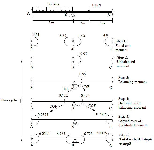
Fig.16.1.
The steps involved in moment distribution method are described bellow and also depicted in Figure 16.1.
Step 1: Fixed end Moments
First assume each span of the continuous beam as fixed beam and calculate the corresponding fixed end moments.
\[M{}_{FAB}=-{{3 \times {5^2}} \over {12}}=-6.25{\rm{ kNm}}\] ; \[M{}_{FBA} = {{3 \times {5^2}} \over {12}} = 6.25{\rm{ kNm}}\]
\[M{}_{FBC}=-{{10 \times 2 \times {3^2}} \over {{5^2}}}=-7.2{\rm{ kNm}}\] ; \[M{}_{FCB}=-{{10 \times 3 \times {2^2}} \over {{5^2}}}=4.8{\rm{ kNm}}\]
Assume \[M{}_{AB}=M{}_{FAB}=-6.25{\rm{ kNm}}\] , \[M{}_{BA}=M{}_{FBA}=6.25{\rm{ kNm}}\] , \[M{}_{BC}=M{}_{FBC}=-7.2{\rm{ kNm}}\] AND \[M{}_{CB}=M{}_{FCB}=4.8{\rm{ kNm}}\]
Step 2: Unbalnced moment
Equilibriuam condition at B is \[M{}_{BA} + M{}_{BC} = 0\] . However initial assumption of \[M{}_{BA}\] and \[M{}_{BC}\] gives,
\[M{}_{BA} + M{}_{BC} = 6.25 - 7.2 =-0.95\]
Therefore at joint B there is an unbalanced moment of - 0.95 kNm.
Since ends A and C are fixed, there is no unbalanced moment at A and C.
Step 3: Balancing moment
Apply a balancing moment of 0.95 kNm at B.
Step 4: Distribution of balancing moment
Applied balancing momnet at B is then distributed among the connecting member i.e., BA and BC in porportion to their stiffness. The distribued moments are determined by multiplying the unbalanced moment by the distribution factor of the respective member.
From lesson 15.1.3 we have,.
\[{k_{BA}} = {{4E{I_{BA}}} \over {{L_{BA}}}} = {{4EI} \over 5}\] and \[{k_{BC}} = {{4E{I_{BC}}} \over {{L_{BC}}}} = {{4EI} \over 5}\]
Distribution factors for BA and BC are,
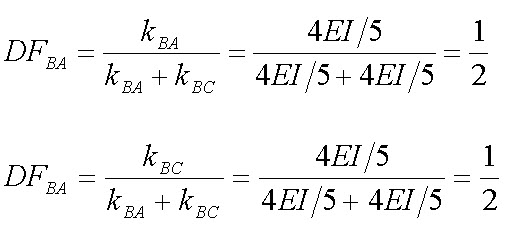
Therefore, distributed moment for BA and BC will be \[0.5 \times 0.95 = 0.475{\rm{ kNm}}\] .
Step 5: Carry over of distributed moment
For member AB, distributed moment at B will cause carried over moment at A. Simiarlary for member BC, distributed moment at B will cause carried over moment at C. These carried over moments are determined by multiplying the distributed moment by the carried over factor of the respective member.
\[{C_{BA}} = {1 \over 2}\] and \[{C_{BC}} = {1 \over 2}\]
Therefore carried over moments are,
At A \[0.5 \times 0.475 = 0.2375{\rm{ kNm}}\]
At C \[0.5 \times 0.475 = 0.2375{\rm{ kNm}}\]
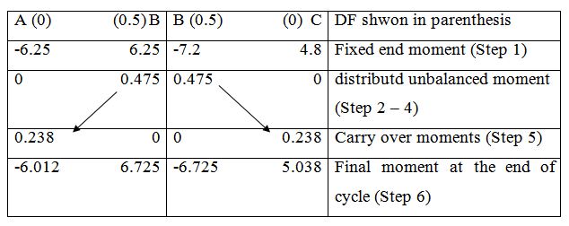
Step 6: Total moment at the end of cycle
Determine the total moment each end.
Total moment = Fixed end moment (Step 1) + Distributed unbalanced moment (Step 4) + Carried over moment (Step 5)
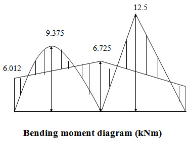
\[M{}_{AB}=-6.25 + 0.2375=-6.0125{\rm{ kNm}}\]
\[M{}_{BA}=6.250 + 0.475=6.725{\rm{ kNm}}\]
\[M{}_{BC}=-7.20 + 0.475=-6.725{\rm{ kNm}}\]
\[M{}_{AB}=4.8 + 0.2375=5.0375{\rm{ kNm}}\]
Step 2 to Step 6 is a complete cycle. At the end of each cycle check whether equilibrium equations are satisfed.
\[M{}_{BA} + M{}_{BC} = 6.725 - 6.725 = 0\] => Equilibrium equation at B is satisfied.
If it is found that there are joints with unbalanced moment then again go to step 2 and repeat the cycle until all the unbalanced moments become zero.
Generally the entire calculation in moment distribution method is done in a tabular form as illustrated bellow.
Suggested Readings
-
Hbbeler, R. C. (2002). Structural Analysis, Pearson Education (Singapore) Pte. Ltd.,Delhi.
-
Jain, A.K., Punmia, B.C., Jain, A.K., (2004). Theory of Structures. Twelfth Edition, Laxmi Publications.
-
Menon, D., (2008), Structural Analysis, Narosa Publishing House Pvt. Ltd., New Delhi.
-
Hsieh, Y.Y., (1987), Elementry Theory of Structures , Third Ddition, Prentrice Hall.
Last modified: Thursday, 19 September 2013, 5:08 AM