Site pages
Current course
Participants
General
MODULE 1. Analysis of Statically Determinate Beams
MODULE 2. Analysis of Statically Indeterminate Beams
MODULE 3. Columns and Struts
MODULE 4. Riveted and Welded Connections
MODULE 5. Stability Analysis of Gravity Dams
Keywords
LESSON 15. Displacement Method: Moment Distribution Method – 1
In slope-deflection method the unknown displacements/rotations are obtained by solving a set of algebraic equations. This becomes cumbersome for structures with large number of members. In such cases the Moment distribution method, also known as the Hardy Cross method (named after Prof. Hardy Cross), provides a convenient means for analyzing the structures in an iterative way. In this lesson we will formulate the basic ingredients of Moment distribution method. Illustration of the general procedure and examples will be discussed in the subsequent lessons.
Sign Convention
For the development and application of Moment Dsitribution Method we will use similar sign convention as in the case of Slope-Deflection Method.
Moment: At the end of a member clockwise moment is positive.
Transverse displacement: Transverse displacement in upward direction is positive.
Rotation: Rotation in anti-clockwise direction is positive.
The above sign convention is depicted in Figure 15.1.
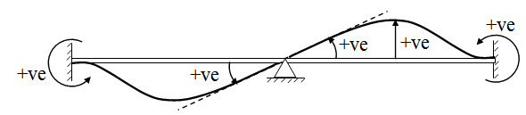
Fig. 15.1.
15.1 Absolute and Relative Stiffness
Stiffness of a member may be defined as the force/moment required to cause unit displacement/rotation. The central idea of Moment distribution method is to distribute moment at any joint, among the connenting members (members meeting at that joint) according to their rotational stiffnesses. In this section we will derive the expressions of rotational stifness of member with different support conditions.
15.1.1 Beam Hinged at Both Ends
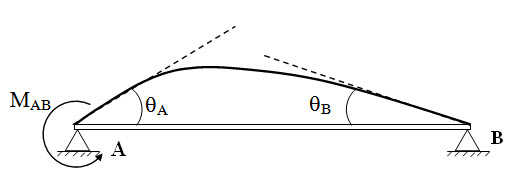
Fig. 15.2.
Slope deflection equation at A and B (δ = 0),
\[{M_{AB}} = {{2EI} \over L}\left( {2{\theta _A} + {\theta _B}} \right)\] (15.1)
\[{M_{BA}} = {{2EI} \over L}\left( {{\theta _A} + 2{\theta _B}} \right)\] (15.2)
Now, at B, equilibrium equation is,MBA = 0 . Therefore form equaition (2), we have,
\[{\theta _B}=-{1 \over 2}{\theta _A}\] .
Substituting, θB = -θA/2 in equation (1), we have,
\[{M_{AB}} = {{2EI} \over L}\left( {2{\theta _A} - {{{\theta _A}} \over 2}} \right)\]
\[\Rightarrow {M_{AB}} = {{3EI} \over L}{\theta _A}\]
Absolute Stiffness \[k = {{3EI} \over L}\]
15.1.2 Beam Hinged at one End and Fixed at other End
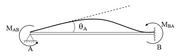
Fig. 15.3.
Slope deflection equation at A and B (qB = 0, d = 0),
\[{M_{AB}} = {{4EI} \over L}{\theta _A}\] (15.3)
\[{M_{BA}} = {{2EI} \over L}{\theta _A}\] (15.4)
From equations (3) and (4), we have,
\[{M_{BA}} = {1 \over 2}{M_{AB}}\] . (15.5)
Absolute Stiffness \[k = {{4EI} \over L}\]
15.1.3 Several members meeting at a joint
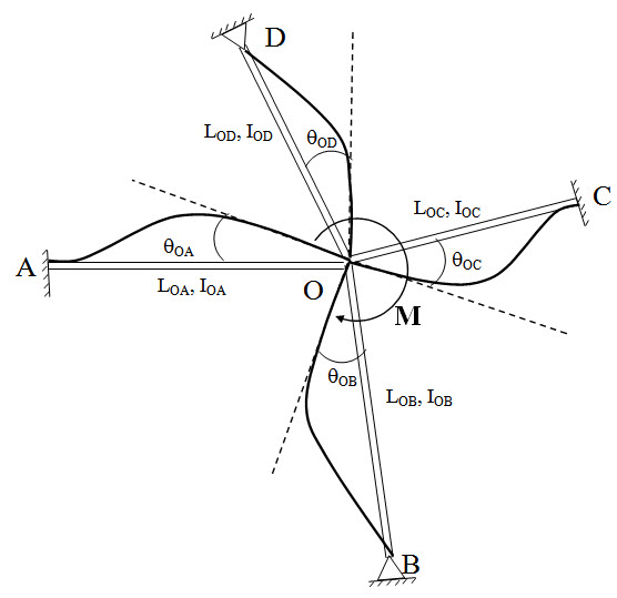
Fig. 15.4.
Figure 15.4 shows, four members (for illustration purpose only four members are taken, but the theory is applicable for any number of members), AO, BO, CO and DO meeting at O. LOA, LOB, LOC, and LOD are the length and IOA, IOB, IOC, and IOD are the second moment of area of the respective members. Support A, C are fixed and B, D are hinged. An external moment M is applied at O. The moment M will be distributed among all the members meeting at O. Suppose MOA, MOB, MOC, and MOD are the corresponding distribution.
Compatibility condition at O,
\[{\theta _{OA}} = {\theta _{OB}} = {\theta _{OC}} = {\theta _{OD}} = \theta \] (15.6)
Equilibrium condition at O,
\[{M_{OA}} = {M_{OB}} = {M_{OC}} = {M_{OD}} = M\] (15.7)
Now from the previous tow cases, we may express MOA, MOB, MOC, and MOD as,
\[{M_{OA}} = {{4E{I_{OA}}} \over {{L_{OA}}}}\theta={k_{OA}}\theta \] (15.8)
\[{M_{OB}} = {{3E{I_{OB}}} \over {{L_{OB}}}}\theta={k_{OB}}\theta \] (15.9)
From Equations (8a) – (8b),
\[{M_{OA}}:{M_{OB}}:{M_{OC}}:{M_{OD}}::{k_{OA}}:{k_{OB}}:{k_{OC}}:{k_{OD}}\] (15.30)
From equations (7) and (9),
\[{M_{OA}} = {{{k_{OA}}} \over {{k_{OA}} + {k_{OB}} + {k_{OC}} + {k_{OD}}}}M = {{{k_{OA}}} \over {\sum k }}M\]
\[{M_{OA}} = {{{k_{OB}}} \over {{k_{OA}} + {k_{OB}} + {k_{OC}} + {k_{OD}}}}M = {{{k_{OB}}} \over {\sum k }}M\]
\[{M_{OA}} = {{{k_{OC}}} \over {{k_{OA}} + {k_{OB}} + {k_{OC}} + {k_{OD}}}}M = {{{k_{OC}}} \over {\sum k }}M\]
\[{M_{OA}} = {{{k_{OD}}} \over {{k_{OA}} + {k_{OB}} + {k_{OC}} + {k_{OD}}}}M = {{{k_{OD}}} \over {\sum k }}M\]
Therefore, moment acting at a joint will be divided amongst the connecting members in proportion to their stiffness.
The factors \[{{{k_{OA}}} \over {\sum k }}\] , \[{{{k_{OB}}} \over {\sum k }}\] , \[{{{k_{OC}}} \over {\sum k }}\] , and \[{{{k_{OD}}} \over {\sum k }}\] are called distribution factor (DF) and moments \[{M_{OA}}\] , \[{M_{OB}}\] , \[{M_{OC}}\] , and \[{M_{OD}}\] are called distributed moments.
15.1.4 Carry Over Factor
Consider a fixed beam AB as shown bellow. Suppose the rotational constraint of joint A is released and a balancing moment MAB is applied at A. Then MAB will cause a moment MBA at B.
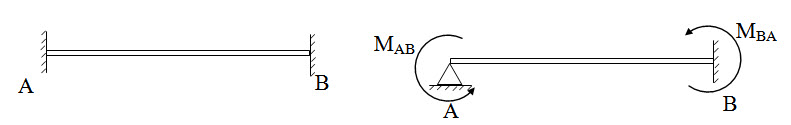
Fig. 15.5.
The carry over factor is defined as,
\[{C_{AB}} = {{{M_{BA}}} \over {{M_{AB}}}}\]
From 15.1.2 we have,
\[{C_{AB}} = {{{M_{BA}}} \over {{M_{AB}}}} = {1 \over 2}\]
Here, \[{M_{BA}}\] is called caried over momnet at B due to \[{M_{AB}}\] at A.
Suggested Readings
Hbbeler, R. C. (2002). Structural Analysis, Pearson Education (Singapore) Pte. Ltd.,Delhi.
Jain, A.K., Punmia, B.C., Jain, A.K., (2004). Theory of Structures. Twelfth Edition, Laxmi Publications.
Menon, D., (2008), Structural Analysis, Narosa Publishing House Pvt. Ltd., New Delhi.
Hsieh, Y.Y., (1987), Elementry Theory of Structures , Third Ddition, Prentrice Hall.
Last modified: Wednesday, 18 September 2013, 11:04 AM